Note:
The chapter describes functions for image processing and analysis.
Most of the functions work with 2d arrays of pixels. We refer the arrays
as "images" however they do not neccesserily have to be IplImage’s, they may
be CvMat’s or CvMatND’s as well.
Calculates first, second, third or mixed image derivatives using extended Sobel operator
void cvSobel( const CvArr* src, CvArr* dst, int xorder, int yorder, int aperture_size=3 );
aperture_size=1 3x1 or 1x3 kernel is used (Gaussian smoothing is not done).
There is also special value CV_SCHARR (=-1) that corresponds to 3x3 Scharr filter that may
give more accurate results than 3x3 Sobel. Scharr aperture is:
| -3 0  3|
|-10 0 10|
| -3 0  3|
for x-derivative or transposed for y-derivative.
The function cvSobel calculates the image derivative by convolving the image
with the appropriate kernel:
dst(x,y) = dxorder+yodersrc/dxxorder•dyyorder |(x,y)The Sobel operators combine Gaussian smoothing and differentiation so the result is more or less robust to the noise. Most often, the function is called with (xorder=1, yorder=0, aperture_size=3) or (xorder=0, yorder=1, aperture_size=3) to calculate first x- or y- image derivative. The first case corresponds to
  |-1  0  1|
  |-2  0  2|
  |-1  0  1|
kernel and the second one corresponds to
  |-1 -2 -1|
  | 0  0  0|
  | 1  2  1|
or
  | 1  2  1|
  | 0  0  0|
  |-1 -2 -1|
kernel, depending on the image origin (
origin field of IplImage structure).
No scaling is done, so the destination image usually has larger by absolute value numbers than
the source image. To avoid overflow, the function requires 16-bit destination image if
the source image is 8-bit. The result can be converted back to 8-bit using cvConvertScale or
cvConvertScaleAbs functions. Besides 8-bit images the function
can process 32-bit floating-point images.
Both source and destination must be single-channel images of equal size or ROI size.
Calculates Laplacian of the image
void cvLaplace( const CvArr* src, CvArr* dst, int aperture_size=3 );
The function cvLaplace calculates Laplacian of the source image by summing
second x- and y- derivatives calculated using Sobel operator:
dst(x,y) = d2src/dx2 + d2src/dy2
Specifying aperture_size=1 gives the fastest variant that is equal to
convolving the image with the following kernel:
|0  1  0|
|1 -4  1|
|0  1  0|
Similar to cvSobel function, no scaling is done and the same combinations of input and output formats are supported.
Implements Canny algorithm for edge detection
void cvCanny( const CvArr* image, CvArr* edges, double threshold1,
              double threshold2, int aperture_size=3 );
The function cvCanny finds the edges on the input image image and marks them in the
output image edges using the Canny algorithm. The smallest of threshold1 and
threshold2 is used for edge linking, the largest - to find initial segments of strong edges.
Calculates feature map for corner detection
void cvPreCornerDetect( const CvArr* image, CvArr* corners, int aperture_size=3 );
The function cvPreCornerDetect calculates the function
Dx2Dyy+Dy2Dxx - 2DxDyDxy
where D? denotes one of the first image derivatives and D?? denotes a second image
derivative. The corners can be found as local maximums of the function:
// assume that the image is floating-point
IplImage* corners = cvCloneImage(image);
IplImage* dilated_corners = cvCloneImage(image);
IplImage* corner_mask = cvCreateImage( cvGetSize(image), 8, 1 );
cvPreCornerDetect( image, corners, 3 );
cvDilate( corners, dilated_corners, 0, 1 );
cvSubS( corners, dilated_corners, corners );
cvCmpS( corners, 0, corner_mask, CV_CMP_GE );
cvReleaseImage( &corners );
cvReleaseImage( &dilated_corners );
Calculates eigenvalues and eigenvectors of image blocks for corner detection
void cvCornerEigenValsAndVecs( const CvArr* image, CvArr* eigenvv,
                               int block_size, int aperture_size=3 );
For every pixel The function cvCornerEigenValsAndVecs considers
block_size × block_size neigborhood S(p). It calcualtes
covariation matrix of derivatives over the neigborhood as:
    | sumS(p)(dI/dx)2   sumS(p)(dI/dx•dI/dy)|
M = |                                 |
    | sumS(p)(dI/dx•dI/dy)  sumS(p)(dI/dy)2 |
After that it finds eigenvectors and eigenvalues of the matrix and stores
them into destination image in form
(λ1, λ2, x1, y1, x2, y2),
where
λ1, λ2 - eigenvalues of M; not sorted
(x1, y1) - eigenvector corresponding to λ1
(x2, y2) - eigenvector corresponding to λ2
Calculates minimal eigenvalue of gradient matrices for corner detection
void cvCornerMinEigenVal( const CvArr* image, CvArr* eigenval, int block_size, int aperture_size=3 );
image
The function cvCornerMinEigenVal is similar to cvCornerEigenValsAndVecs but
it calculates and stores only the minimal eigen value of derivative covariation matrix for every pixel,
i.e. min(λ1, λ2) in terms of the previous function.
Harris edge detector
void cvCornerHarris( const CvArr* image, CvArr* harris_responce,
                     int block_size, int aperture_size=3, double k=0.04 );
image
The function cvCornerHarris runs the Harris edge detector on image. Similarly to
cvCornerMinEigenVal and
cvCornerEigenValsAndVecs, for each pixel it calculates 2x2 gradient
covariation matrix M over block_size×block_size neighborhood.
Then, it stores
det(M) - k*trace(M)2to the destination image. Corners in the image can be found as local maxima of the destination image.
Refines corner locations
void cvFindCornerSubPix( const CvArr* image, CvPoint2D32f* corners,
                         int count, CvSize win, CvSize zero_zone,
                         CvTermCriteria criteria );
win=(5,5) then
5*2+1 × 5*2+1 = 11 × 11 search window is used.
criteria may specify either of or both the maximum
number of iteration and the required accuracy.
The function cvFindCornerSubPix iterates to find the sub-pixel accurate location
of corners, or radial saddle points, as shown in on the picture below.
Sub-pixel accurate corner locator is based on the observation that every vector
from the center q to a point p located within a neighborhood of q is orthogonal
to the image gradient at p subject to image and measurement noise. Consider the expression:
εi=DIpiT•(q-pi)where
DIpi is the image gradient
at the one of the points pi in a neighborhood of q.
The value of q is to be found such that εi is minimized.
A system of equations may be set up with εi' set to zero:
sumi(DIpi•DIpiT)•q - sumi(DIpi•DIpiT•pi) = 0
where the gradients are summed within a neighborhood ("search window") of q.
Calling the first gradient term G and the second gradient term b gives:
q=G-1•b
The algorithm sets the center of the neighborhood window at this new center q
and then iterates until the center keeps within a set threshold.
Determines strong corners on image
void cvGoodFeaturesToTrack( const CvArr* image, CvArr* eig_image, CvArr* temp_image,
                            CvPoint2D32f* corners, int* corner_count,
                            double quality_level, double min_distance,
                            const CvArr* mask=NULL, int block_size=3,
                            int use_harris=0, double k=0.04 );
image.
eig_image.
use_harris≠0
The function cvGoodFeaturesToTrack finds corners with big eigenvalues in the
image. The function first calculates the minimal eigenvalue for every source image pixel
using cvCornerMinEigenVal function and stores them in eig_image.
Then it performs non-maxima suppression (only local maxima in 3x3 neighborhood remain).
The next step is rejecting the corners with the
minimal eigenvalue less than quality_level•max(eig_image(x,y)). Finally,
the function ensures that all the corners found are distanced enough one from
another by considering the corners (the most strongest corners are considered first)
and checking that the distance between the newly considered feature and the features considered earlier
is larger than min_distance. So, the function removes the features than are too close
to the stronger features.
Reads raster line to buffer
int cvSampleLine( const CvArr* image, CvPoint pt1, CvPoint pt2,
                  void* buffer, int connectivity=8 );
pt2.x-pt1.x|+1, |pt2.y-pt1.y|+1 ) points in case
of 8-connected line and |pt2.x-pt1.x|+|pt2.y-pt1.y|+1 in case
of 4-connected line.
The function cvSampleLine implements a particular case of application of line
iterators. The function reads all the image points lying on the line between pt1
and pt2, including the ending points, and stores them into the buffer.
Retrieves pixel rectangle from image with sub-pixel accuracy
void cvGetRectSubPix( const CvArr* src, CvArr* dst, CvPoint2D32f center );
The function cvGetRectSubPix extracts pixels from src:
dst(x, y) = src(x + center.x - (width(dst)-1)*0.5, y + center.y - (height(dst)-1)*0.5)
where the values of pixels at non-integer coordinates are retrieved using bilinear interpolation. Every channel of multiple-channel images is processed independently. Whereas the rectangle center must be inside the image, the whole rectangle may be partially occluded. In this case, the replication border mode is used to get pixel values beyond the image boundaries.
Retrieves pixel quadrangle from image with sub-pixel accuracy
void cvGetQuadrangleSubPix( const CvArr* src, CvArr* dst, const CvMat* map_matrix );
A|b] (see the discussion).
The function cvGetQuadrangleSubPix extracts pixels from src at sub-pixel accuracy
and stores them to dst as follows:
dst(x, y)= src( A11x'+A12y'+b1, A21x'+A22y'+b2), whereAandbare taken frommap_matrix| A11 A12 b1 | map_matrix = | | | A21 A22 b2 |, x'=x-(width(dst)-1)*0.5, y'=y-(height(dst)-1)*0.5
where the values of pixels at non-integer coordinates A•(x,y)T+b are retrieved using bilinear interpolation. When the function needs pixels outside of the image, it uses replication border mode to reconstruct the values. Every channel of multiple-channel images is processed independently.
Resizes image
void cvResize( const CvArr* src, CvArr* dst, int interpolation=CV_INTER_LINEAR );
CV_INTER_NN method.
The function cvResize resizes image src so that it fits exactly to dst.
If ROI is set, the function consideres the ROI as supported as usual.
Applies affine transformation to the image
void cvWarpAffine( const CvArr* src, CvArr* dst, const CvMat* map_matrix,
                   int flags=CV_INTER_LINEAR+CV_WARP_FILL_OUTLIERS,
                   CvScalar fillval=cvScalarAll(0) );
fillval.
matrix is inverse transform from destination image
to source and, thus, can be used directly for pixel interpolation. Otherwise,
the function finds the inverse transform from map_matrix.
The function cvWarpAffine transforms source image using the specified
matrix:
dst(x’,y’)<-src(x,y)
(x’,y’)T=map_matrix•(x,y,1)T+b if CV_WARP_INVERSE_MAP is not set,
(x, y)T=map_matrix•(x’,y&apos,1)T+b otherwise
The function is similar to cvGetQuadrangleSubPix but they are not exactly the same. cvWarpAffine requires input and output image have the same data type, has larger overhead (so it is not quite suitable for small images) and can leave part of destination image unchanged. While cvGetQuadrangleSubPix may extract quadrangles from 8-bit images into floating-point buffer, has smaller overhead and always changes the whole destination image content.
To transform a sparse set of points, use cvTransform function from cxcore.
Calculates affine transform from 3 corresponding points
CvMat* cvGetAffineTransform( const CvPoint2D32f* src, const CvPoint2D32f* dst,
                             CvMat* map_matrix );
The function cvGetAffineTransform calculates the
matrix of an affine transform such that:
(x'i,y'i)T=map_matrix•(xi,yi,1)T
where dst(i)=(x'i,y'i), src(i)=(xi,yi), i=0..2.
Calculates affine matrix of 2d rotation
CvMat* cv2DRotationMatrix( CvPoint2D32f center, double angle,
                           double scale, CvMat* map_matrix );
The function cv2DRotationMatrix calculates matrix:
[  α  β  |  (1-α)*center.x - β*center.y ]
[ -β  α  |  β*center.x + (1-α)*center.y ]

where α=scale*cos(angle), β=scale*sin(angle)
The transformation maps the rotation center to itself. If this is not the purpose, the shift should be adjusted.
Applies perspective transformation to the image
void cvWarpPerspective( const CvArr* src, CvArr* dst, const CvMat* map_matrix,
                        int flags=CV_INTER_LINEAR+CV_WARP_FILL_OUTLIERS,
                        CvScalar fillval=cvScalarAll(0) );
fillval.
matrix is inverse transform from destination image
to source and, thus, can be used directly for pixel interpolation. Otherwise,
the function finds the inverse transform from map_matrix.
The function cvWarpPerspective transforms source image using
the specified matrix:
dst(x’,y’)<-src(x,y)
(t•x’,t•y’,t)T=map_matrix•(x,y,1)T+b if CV_WARP_INVERSE_MAP is not set,
(t•x, t•y, t)T=map_matrix•(x’,y&apos,1)T+b otherwise
For a sparse set of points use cvPerspectiveTransform function from cxcore.
Calculates perspective transform from 4 corresponding points
CvMat* cvGetPerspectiveTransform( const CvPoint2D32f* src, const CvPoint2D32f* dst,
                                  CvMat* map_matrix );

#define cvWarpPerspectiveQMatrix cvGetPerspectiveTransform
The function cvGetPerspectiveTransform calculates
matrix of perspective transform such that:
(ti•x'i,ti•y'i,ti)T=map_matrix•(xi,yi,1)T
where dst(i)=(x'i,y'i), src(i)=(xi,yi), i=0..3.
Applies generic geometrical transformation to the image
void cvRemap( const CvArr* src, CvArr* dst,
              const CvArr* mapx, const CvArr* mapy,
              int flags=CV_INTER_LINEAR+CV_WARP_FILL_OUTLIERS,
              CvScalar fillval=cvScalarAll(0) );
fillval.
The function cvRemap transforms source image using
the specified map:
dst(x,y)<-src(mapx(x,y),mapy(x,y))
Similar to other geometrical transformations, some interpolation method (specified by user) is used to extract pixels with non-integer coordinates.
Remaps image to log-polar space
void cvLogPolar( const CvArr* src, CvArr* dst,
                 CvPoint2D32f center, double M,
                 int flags=CV_INTER_LINEAR+CV_WARP_FILL_OUTLIERS );
matrix is inverse transform from destination image
to source and, thus, can be used directly for pixel interpolation. Otherwise,
the function finds the inverse transform from map_matrix.
The function cvLogPolar transforms source image using
the following transformation:
Forward transformation (CV_WARP_INVERSE_MAPis not set): dst(phi,rho)<-src(x,y) Inverse transformation (CV_WARP_INVERSE_MAPis set): dst(x,y)<-src(phi,rho), where rho=M*log(sqrt(x2+y2)) phi=atan(y/x)
The function emulates the human "foveal" vision and can be used for fast scale and rotation-invariant template matching, for object tracking etc.
#include <cv.h>
#include <highgui.h>

int main(int argc, char** argv)
{
    IplImage* src;

    if( argc == 2 && (src=cvLoadImage(argv[1],1) != 0 )
    {
        IplImage* dst = cvCreateImage( cvSize(256,256), 8, 3 );
        IplImage* src2 = cvCreateImage( cvGetSize(src), 8, 3 );
        cvLogPolar( src, dst, cvPoint2D32f(src->width/2,src->height/2), 40, CV_INTER_LINEAR+CV_WARP_FILL_OUTLIERS );
        cvLogPolar( dst, src2, cvPoint2D32f(src->width/2,src->height/2), 40, CV_INTER_LINEAR+CV_WARP_FILL_OUTLIERS+CV_WARP_INVERSE_MAP );
        cvNamedWindow( "log-polar", 1 );
        cvShowImage( "log-polar", dst );
        cvNamedWindow( "inverse log-polar", 1 );
        cvShowImage( "inverse log-polar", src2 );
        cvWaitKey();
    }
    return 0;
}
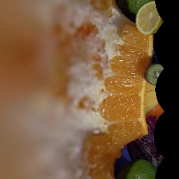
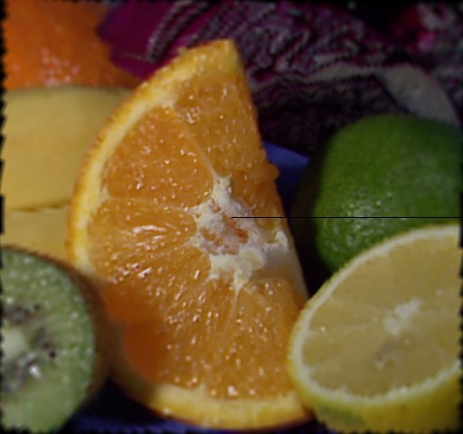
And this is what the program displays when opencv/samples/c/fruits.jpg is passed to it
Creates structuring element
IplConvKernel* cvCreateStructuringElementEx( int cols, int rows, int anchor_x, int anchor_y,
                                             int shape, int* values=NULL );
CV_SHAPE_RECT, a rectangular element;
CV_SHAPE_CROSS, a cross-shaped element;
CV_SHAPE_ELLIPSE, an elliptic element;
CV_SHAPE_CUSTOM, a user-defined element. In this case the parameter values
specifies the mask, that is, which neighbors of the pixel must be considered.
NULL, then all values are considered
non-zero, that is, the element is of a rectangular shape. This parameter is
considered only if the shape is CV_SHAPE_CUSTOM .
The function cv CreateStructuringElementEx allocates and fills the structure
IplConvKernel, which can be used as a structuring element in the morphological
operations.
Deletes structuring element
void cvReleaseStructuringElement( IplConvKernel** element );
The function cvReleaseStructuringElement releases the structure IplConvKernel
that is no longer needed. If *element is NULL, the function has no effect.
Erodes image by using arbitrary structuring element
void cvErode( const CvArr* src, CvArr* dst, IplConvKernel* element=NULL, int iterations=1 );
NULL, a 3×3 rectangular
structuring element is used.
The function cvErode erodes the source image using the specified structuring element
that determines the shape of a pixel neighborhood over which the minimum is taken:
dst=erode(src,element): dst(x,y)=min((x',y') in element))src(x+x',y+y')
The function supports the in-place mode. Erosion can be applied several (iterations)
times. In case of color image each channel is processed independently.
Dilates image by using arbitrary structuring element
void cvDilate( const CvArr* src, CvArr* dst, IplConvKernel* element=NULL, int iterations=1 );
NULL, a 3×3 rectangular
structuring element is used.
The function cvDilate dilates the source image using the specified structuring element
that determines the shape of a pixel neighborhood over which the maximum is taken:
dst=dilate(src,element): dst(x,y)=max((x',y') in element))src(x+x',y+y')
The function supports the in-place mode. Dilation can be applied several (iterations)
times. In case of color image each channel is processed independently.
Performs advanced morphological transformations
void cvMorphologyEx( const CvArr* src, CvArr* dst, CvArr* temp,
                     IplConvKernel* element, int operation, int iterations=1 );
CV_MOP_OPEN - openingCV_MOP_CLOSE - closingCV_MOP_GRADIENT - morphological gradientCV_MOP_TOPHAT - "top hat"CV_MOP_BLACKHAT - "black hat"
The function cvMorphologyEx can perform advanced morphological
transformations using erosion and dilation as basic operations.
Opening:
dst=open(src,element)=dilate(erode(src,element),element)

Closing:
dst=close(src,element)=erode(dilate(src,element),element)

Morphological gradient:
dst=morph_grad(src,element)=dilate(src,element)-erode(src,element)

"Top hat":
dst=tophat(src,element)=src-open(src,element)

"Black hat":
dst=blackhat(src,element)=close(src,element)-src
The temporary image temp is required for morphological gradient and, in case of in-place
operation, for "top hat" and "black hat".
Smooths the image in one of several ways
void cvSmooth( const CvArr* src, CvArr* dst,
               int smoothtype=CV_GAUSSIAN,
               int param1=3, int param2=0, double param3=0, double param4=0 );
param1×param2 neighborhood.
If the neighborhood size may vary, one may precompute integral image with cvIntegral function.
param1×param2 neighborhood with
subsequent scaling by 1/(param1•param2).
param1×param2 Gaussian kernel.
param1×param1 neighborhood (i.e.
the neighborhood is square).
param1 and
space sigma=param2. Information about bilateral filtering
can be found at
http://www.dai.ed.ac.uk/CVonline/LOCAL_COPIES/MANDUCHI1/Bilateral_Filtering.html
param2 is zero, it is set to param1.
              sigma = (n/2 - 1)*0.3 + 0.8, where n=param1 for horizontal kernel,
                                                 n=param2 for vertical kernel.
With the standard sigma for small kernels (3×3 to 7×7) the performance is better.
If param3 is not zero, while param1 and param2
are zeros, the kernel size is calculated from the sigma (to provide accurate enough operation).
param3) sigma in the vertical direction.
The function cvSmooth smooths image using one of several methods. Every of the methods
has some features and restrictions listed below
Blur with no scaling works with single-channel images only and supports accumulation of 8-bit to 16-bit format (similar to cvSobel and cvLaplace) and 32-bit floating point to 32-bit floating-point format.
Simple blur and Gaussian blur support 1- or 3-channel, 8-bit and 32-bit floating point images. These two methods can process images in-place.
Median and bilateral filters work with 1- or 3-channel 8-bit images and can not process images in-place.
Convolves image with the kernel
void cvFilter2D( const CvArr* src, CvArr* dst,
                 const CvMat* kernel,
                 CvPoint anchor=cvPoint(-1,-1));
The function cvFilter2D applies arbitrary linear filter to the image.
In-place operation is supported. When the aperture is partially outside the image, the function
interpolates outlier pixel values from the nearest pixels that is inside the image.
Copies image and makes border around it
void cvCopyMakeBorder( const CvArr* src, CvArr* dst, CvPoint offset,
                       int bordertype, CvScalar value=cvScalarAll(0) );
IPL_BORDER_CONSTANT -
border is filled with the fixed value, passed as last parameter of the function.IPL_BORDER_REPLICATE -
the pixels from the top and bottom rows, the left-most and right-most columns are replicated
to fill the border.IPL_BORDER_REFLECT and IPL_BORDER_WRAP,
are currently unsupported).
bordertype=IPL_BORDER_CONSTANT.
The function cvCopyMakeBorder copies the source 2D array into interior of destination array
and makes a border of the specified type around the copied area.
The function is useful when one needs to emulate border type that is different from the one embedded into a specific
algorithm implementation. For example, morphological functions, as well as most of other filtering functions in OpenCV,
internally use replication border type, while the user may need zero border or a border, filled with 1's or 255's.
Calculates integral images
void cvIntegral( const CvArr* image, CvArr* sum, CvArr* sqsum=NULL, CvArr* tilted_sum=NULL );
W×H, 8-bit or floating-point (32f or 64f) image.
W+1×H+1, 32-bit integer or double precision floating-point (64f).
W+1×H+1, double precision floating-point (64f).
W+1×H+1, the same data type as sum.
The function cvIntegral calculates one or more integral images for the source image as following:
sum(X,Y)=sumx<X,y<Yimage(x,y)

sqsum(X,Y)=sumx<X,y<Yimage(x,y)2

tilted_sum(X,Y)=sumy<Y,abs(x-X)<yimage(x,y)
Using these integral images, one may calculate sum, mean, standard deviation over arbitrary up-right or rotated rectangular region of the image in a constant time, for example:
sumx1<=x<x2,y1<=y<y2image(x,y)=sum(x2,y2)-sum(x1,y2)-sum(x2,y1)+sum(x1,x1)
It makes possible to do a fast blurring or fast block correlation with variable window size etc. In case of multi-channel images sums for each channel are accumulated independently.
Converts image from one color space to another
void cvCvtColor( const CvArr* src, CvArr* dst, int code );
The function cvCvtColor converts input image from one color space to another.
The function ignores colorModel and channelSeq fields of IplImage header,
so the source image color space should be specified correctly (including order of the channels in case
of RGB space, e.g. BGR means 24-bit format with B0 G0 R0 B1 G1 R1 ... layout,
whereas RGB means 24-bit format with R0 G0 B0 R1 G1 B1 ... layout).
The conventional range for R,G,B channel values is:
The function can do the following transformations:
RGB[A]->Gray: Y<-0.299*R + 0.587*G + 0.114*B
Gray->RGB[A]: R<-Y G<-Y B<-Y A<-0
CV_BGR2XYZ, CV_RGB2XYZ, CV_XYZ2BGR, CV_XYZ2RGB):
|X|    |0.412453  0.357580  0.180423| |R|
|Y| <- |0.212671  0.715160  0.072169|*|G|
|Z|    |0.019334  0.119193  0.950227| |B|

|R|    | 3.240479  -1.53715  -0.498535| |X|
|G| <- |-0.969256   1.875991  0.041556|*|Y|
|B|    | 0.055648  -0.204043  1.057311| |Z|

X, Y and Z cover the whole value range (in case of floating-point images Z may exceed 1).
CV_BGR2YCrCb, CV_RGB2YCrCb, CV_YCrCb2BGR, CV_YCrCb2RGB)
Y <- 0.299*R + 0.587*G + 0.114*B
Cr <- (R-Y)*0.713 + delta
Cb <- (B-Y)*0.564 + delta

R <- Y + 1.403*(Cr - delta)
G <- Y - 0.344*(Cr - delta) - 0.714*(Cb - delta)
B <- Y + 1.773*(Cb - delta),

              { 128 for 8-bit images,
where delta = { 32768 for 16-bit images
              { 0.5 for floating-point images

Y, Cr and Cb cover the whole value range.
CV_BGR2HSV, CV_RGB2HSV, CV_HSV2BGR, CV_HSV2RGB)
// In case of 8-bit and 16-bit images
// R, G and B are converted to floating-point format and scaled to fit 0..1 range

V <- max(R,G,B)
S <- (V-min(R,G,B))/V   if V≠0, 0 otherwise

         (G - B)*60/S,  if V=R
H <- 180+(B - R)*60/S,  if V=G
     240+(R - G)*60/S,  if V=B

if H<0 then H<-H+360

On output 0≤V≤1, 0≤S≤1, 0≤H≤360.
The values are then converted to the destination data type:
    8-bit images:
        V <- V*255, S <- S*255, H <- H/2 (to fit to 0..255)
    16-bit images (currently not supported):
        V <- V*65535, S <- S*65535, H <- H
    32-bit images:
        H, S, V are left as is
CV_BGR2HLS, CV_RGB2HLS, CV_HLS2BGR, CV_HLS2RGB)
// In case of 8-bit and 16-bit images
// R, G and B are converted to floating-point format and scaled to fit 0..1 range

Vmax <- max(R,G,B)
Vmin <- min(R,G,B)

L <- (Vmax + Vmin)/2

S <- (Vmax - Vmin)/(Vmax + Vmin)  if L < 0.5
     (Vmax - Vmin)/(2 - (Vmax + Vmin))  if L ≥ 0.5

         (G - B)*60/S,  if Vmax=R
H <- 180+(B - R)*60/S,  if Vmax=G
     240+(R - G)*60/S,  if Vmax=B

if H<0 then H<-H+360

On output 0≤L≤1, 0≤S≤1, 0≤H≤360.
The values are then converted to the destination data type:
    8-bit images:
        L <- L*255, S <- S*255, H <- H/2
    16-bit images (currently not supported):
        L <- L*65535, S <- S*65535, H <- H
    32-bit images:
        H, L, S are left as is
CV_BGR2Lab, CV_RGB2Lab, CV_Lab2BGR, CV_Lab2RGB)
// In case of 8-bit and 16-bit images
// R, G and B are converted to floating-point format and scaled to fit 0..1 range

// convert R,G,B to CIE XYZ
|X|    |0.412453  0.357580  0.180423| |R|
|Y| <- |0.212671  0.715160  0.072169|*|G|
|Z|    |0.019334  0.119193  0.950227| |B|

X <- X/Xn, where Xn = 0.950456
Z <- Z/Zn, where Zn = 1.088754

L <- 116*Y1/3      for Y>0.008856
L <- 903.3*Y      for Y<=0.008856

a <- 500*(f(X)-f(Y)) + delta
b <- 200*(f(Y)-f(Z)) + delta
where f(t)=t1/3              for t>0.008856
      f(t)=7.787*t+16/116   for t<=0.008856


where delta = 128 for 8-bit images,
              0 for floating-point images

On output 0≤L≤100, -127≤a≤127, -127≤b≤127
The values are then converted to the destination data type:
    8-bit images:
        L <- L*255/100, a <- a + 128, b <- b + 128
    16-bit images are currently not supported
    32-bit images:
        L, a, b are left as is
CV_BGR2Luv, CV_RGB2Luv, CV_Luv2BGR, CV_Luv2RGB)
// In case of 8-bit and 16-bit images
// R, G and B are converted to floating-point format and scaled to fit 0..1 range

// convert R,G,B to CIE XYZ
|X|    |0.412453  0.357580  0.180423| |R|
|Y| <- |0.212671  0.715160  0.072169|*|G|
|Z|    |0.019334  0.119193  0.950227| |B|

L <- 116*Y1/3-16   for Y>0.008856
L <- 903.3*Y      for Y<=0.008856

u' <- 4*X/(X + 15*Y + 3*Z)
v' <- 9*Y/(X + 15*Y + 3*Z)

u <- 13*L*(u' - un), where un=0.19793943
v <- 13*L*(v' - vn), where vn=0.46831096

On output 0≤L≤100, -134≤u≤220, -140≤v≤122
The values are then converted to the destination data type:
    8-bit images:
        L <- L*255/100, u <- (u + 134)*255/354, v <- (v + 140)*255/256
    16-bit images are currently not supported
    32-bit images:
        L, u, v are left as is
The above formulae for converting RGB to/from various color spaces have been taken
from multiple sources on Web, primarily from Color Space Conversions ([Ford98])
document at Charles Poynton site.
CV_BayerBG2BGR, CV_BayerGB2BGR, CV_BayerRG2BGR, CV_BayerGR2BGR,

                CV_BayerBG2RGB, CV_BayerGB2RGB, CV_BayerRG2RGB, CV_BayerGR2RGB
)
Bayer pattern is widely used in CCD and CMOS cameras. It allows to get color picture out of a single plane where R,G and B pixels (sensors of a particular component) are interleaved like this:
R |
G |
R |
G |
R |
G |
B |
G |
B |
G |
R |
G |
R |
G |
R |
G |
B |
G |
B |
G |
R |
G |
R |
G |
R |
G |
B |
G |
B |
G |
The output RGB components of a pixel are interpolated from 1, 2 or 4 neighbors of the pixel having the same color. There are several modifications of the above pattern that can be achieved by shifting the pattern one pixel left and/or one pixel up. The two letters C1 and C2 in the conversion constants CV_BayerC1C22{BGR|RGB} indicate the particular pattern type - these are components from the second row, second and third columns, respectively. For example, the above pattern has very popular "BG" type.
Applies fixed-level threshold to array elements
void cvThreshold( const CvArr* src, CvArr* dst, double threshold,
                  double max_value, int threshold_type );
src or 8-bit.
CV_THRESH_BINARY and
CV_THRESH_BINARY_INV thresholding types.
The function cvThreshold applies fixed-level thresholding to single-channel array.
The function is typically used to get bi-level (binary) image out of grayscale image
(cvCmpS
could be also used for this purpose) or for removing a noise, i.e. filtering out pixels with too small or too large values.
There are several types of thresholding the function supports that are determined by threshold_type:
threshold_type=CV_THRESH_BINARY:
dst(x,y) = max_value, if src(x,y)>threshold
           0, otherwise

threshold_type=CV_THRESH_BINARY_INV:
dst(x,y) = 0, if src(x,y)>threshold
           max_value, otherwise

threshold_type=CV_THRESH_TRUNC:
dst(x,y) = threshold, if src(x,y)>threshold
           src(x,y), otherwise

threshold_type=CV_THRESH_TOZERO:
dst(x,y) = src(x,y), if src(x,y)>threshold
           0, otherwise

threshold_type=CV_THRESH_TOZERO_INV:
dst(x,y) = 0, if src(x,y)>threshold
           src(x,y), otherwise
And this is the visual description of thresholding types:
Applies adaptive threshold to array
void cvAdaptiveThreshold( const CvArr* src, CvArr* dst, double max_value,
                          int adaptive_method=CV_ADAPTIVE_THRESH_MEAN_C,
                          int threshold_type=CV_THRESH_BINARY,
                          int block_size=3, double param1=5 );
CV_THRESH_BINARY and CV_THRESH_BINARY_INV.
CV_ADAPTIVE_THRESH_MEAN_C
or CV_ADAPTIVE_THRESH_GAUSSIAN_C (see the discussion).
CV_THRESH_BINARY,
CV_THRESH_BINARY_INV
CV_ADAPTIVE_THRESH_MEAN_C and CV_ADAPTIVE_THRESH_GAUSSIAN_C
it is a constant subtracted from mean or weighted mean (see the discussion), though it may be negative.
The function cvAdaptiveThreshold transforms grayscale image to binary image according to
the formulae:
threshold_type=CV_THRESH_BINARY:
dst(x,y) = max_value, if src(x,y)>T(x,y)
           0, otherwise

threshold_type=CV_THRESH_BINARY_INV:
dst(x,y) = 0, if src(x,y)>T(x,y)
           max_value, otherwise
where TI is a threshold calculated individually for each pixel.
For the method CV_ADAPTIVE_THRESH_MEAN_C it is a mean of block_size × block_size
pixel neighborhood, subtracted by param1.
For the method CV_ADAPTIVE_THRESH_GAUSSIAN_C it is a weighted sum (gaussian) of
block_size × block_size pixel neighborhood, subtracted by param1.
Downsamples image
void cvPyrDown( const CvArr* src, CvArr* dst, int filter=CV_GAUSSIAN_5x5 );
CV_GAUSSIAN_5x5 is
currently supported.
The function cvPyrDown performs downsampling step of Gaussian pyramid
decomposition. First it convolves source image with the specified filter and
then downsamples the image by rejecting even rows and columns.
Upsamples image
void cvPyrUp( const CvArr* src, CvArr* dst, int filter=CV_GAUSSIAN_5x5 );
CV_GAUSSIAN_5x5 is
currently supported.
The function cvPyrUp performs up-sampling step of Gaussian pyramid decomposition.
First it upsamples the source image by injecting even zero rows and columns and
then convolves result with the specified filter multiplied by 4 for
interpolation. So the destination image is four times larger than the source
image.
Connected component
    typedef struct CvConnectedComp
    {
        double area; /* area of the segmented component */
        float value; /* gray scale value of the segmented component */
        CvRect rect; /* ROI of the segmented component */
    } CvConnectedComp;
Fills a connected component with given color
void cvFloodFill( CvArr* image, CvPoint seed_point, CvScalar new_val,
                  CvScalar lo_diff=cvScalarAll(0), CvScalar up_diff=cvScalarAll(0),
                  CvConnectedComp* comp=NULL, int flags=4, CvArr* mask=NULL );
#define CV_FLOODFILL_FIXED_RANGE (1 << 16)
#define CV_FLOODFILL_MASK_ONLY   (1 << 17)
new_val is ignored),
but the fills mask (that must be non-NULL in this case).
image. If not NULL, the function uses and updates the mask, so user takes responsibility of
initializing mask content. Floodfilling can't go across
non-zero pixels in the mask, for example, an edge detector output can be used as a mask
to stop filling at edges. Or it is possible to use the same mask in multiple calls to the function
to make sure the filled area do not overlap. Note: because mask is larger than the filled image,
pixel in mask that corresponds to (x,y) pixel in image
will have coordinates (x+1,y+1).
The function cvFloodFill fills a connected component starting from the seed point
with the specified color. The connectivity is determined by the closeness of pixel values.
The pixel at (x, y) is considered to belong to the repainted domain if:
src(x',y')-lo_diff<=src(x,y)<=src(x',y')+up_diff,     grayscale image, floating range
src(seed.x,seed.y)-lo<=src(x,y)<=src(seed.x,seed.y)+up_diff, grayscale image, fixed range

src(x',y')r-lo_diffr<=src(x,y)r<=src(x',y')r+up_diffr and
src(x',y')g-lo_diffg<=src(x,y)g<=src(x',y')g+up_diffg and
src(x',y')b-lo_diffb<=src(x,y)b<=src(x',y')b+up_diffb, color image, floating range

src(seed.x,seed.y)r-lo_diffr<=src(x,y)r<=src(seed.x,seed.y)r+up_diffr and
src(seed.x,seed.y)g-lo_diffg<=src(x,y)g<=src(seed.x,seed.y)g+up_diffg and
src(seed.x,seed.y)b-lo_diffb<=src(x,y)b<=src(seed.x,seed.y)b+up_diffb, color image, fixed range
where
src(x',y') is value of one of pixel neighbors.
That is, to be added to the connected component, a pixel’s color/brightness should be close enough to:
Finds contours in binary image
int cvFindContours( CvArr* image, CvMemStorage* storage, CvSeq** first_contour,
                    int header_size=sizeof(CvContour), int mode=CV_RETR_LIST,
                    int method=CV_CHAIN_APPROX_SIMPLE, CvPoint offset=cvPoint(0,0) );
binary. To get such a binary image
from grayscale, one may use cvThreshold, cvAdaptiveThreshold or cvCanny.
The function modifies the source image content.
method=CV_CHAIN_CODE,
and >=sizeof(CvContour) otherwise.
CV_RETR_EXTERNAL - retrive only the extreme outer contours
CV_RETR_LIST - retrieve all the contours and puts them in the list
CV_RETR_CCOMP - retrieve all the contours and organizes them into two-level hierarchy:
top level are external boundaries of the components, second level are bounda
boundaries of the holes
CV_RETR_TREE - retrieve all the contours and reconstructs the full hierarchy of
nested contours
CV_RETR_RUNS, which uses
built-in approximation).
CV_CHAIN_CODE - output contours in the Freeman chain code. All other methods output polygons
(sequences of vertices).
CV_CHAIN_APPROX_NONE - translate all the points from the chain code into
points;
CV_CHAIN_APPROX_SIMPLE - compress horizontal, vertical, and diagonal segments,
that is, the function leaves only their ending points;
CV_CHAIN_APPROX_TC89_L1,CV_CHAIN_APPROX_TC89_KCOS - apply one of the flavors of
Teh-Chin chain approximation algorithm.
CV_LINK_RUNS - use completely different contour retrieval algorithm via
linking of horizontal segments of 1’s. Only CV_RETR_LIST retrieval mode can be used
with this method.
- offset
- Offset, by which every contour point is shifted. This is useful if the contours are extracted from
the image ROI and then they should be analyzed in the whole image context.
The function cvFindContours retrieves contours from the binary image and returns
the number of retrieved contours. The pointer first_contour is filled by the function.
It will contain pointer to the first most outer contour or NULL if no contours is detected (if the image is completely black).
Other contours may be reached from first_contour using h_next and v_next links.
The sample in cvDrawContours discussion shows how to use contours for connected component
detection. Contours can be also used for shape analysis and object recognition - see squares.c
in OpenCV sample directory.
StartFindContours
Initializes contour scanning process
CvContourScanner cvStartFindContours( CvArr* image, CvMemStorage* storage,
int header_size=sizeof(CvContour),
int mode=CV_RETR_LIST,
int method=CV_CHAIN_APPROX_SIMPLE,
CvPoint offset=cvPoint(0,0) );
- image
- The source 8-bit single channel binary image.
- storage
- Container of the retrieved contours.
- header_size
- Size of the sequence header, >=sizeof(CvChain) if
method=CV_CHAIN_CODE,
and >=sizeof(CvContour) otherwise.
- mode
- Retrieval mode; see cvFindContours.
- method
- Approximation method. It has the same meaning as in cvFindContours,
but CV_LINK_RUNS can not be used here.
- offset
- ROI offset; see cvFindContours.
The function cvStartFindContours initializes and returns pointer to the contour
scanner. The scanner is used further in cvFindNextContour to retrieve the rest of contours.
FindNextContour
Finds next contour in the image
CvSeq* cvFindNextContour( CvContourScanner scanner );
- scanner
- Contour scanner initialized by The function
cvStartFindContours .
The function cvFindNextContour locates and retrieves the next contour in the image and
returns pointer to it. The function returns NULL, if there is no more contours.
SubstituteContour
Replaces retrieved contour
void cvSubstituteContour( CvContourScanner scanner, CvSeq* new_contour );
- scanner
- Contour scanner initialized by the function cvStartFindContours .
- new_contour
- Substituting contour.
The function cvSubstituteContour replaces the retrieved contour, that was returned
from the preceding call of The function cvFindNextContour and stored inside
the contour scanner state, with the user-specified contour. The contour is
inserted into the resulting structure, list, two-level hierarchy, or tree,
depending on the retrieval mode. If the parameter new_contour=NULL, the retrieved
contour is not included into the resulting structure, nor all of its children
that might be added to this structure later.
EndFindContours
Finishes scanning process
CvSeq* cvEndFindContours( CvContourScanner* scanner );
- scanner
- Pointer to the contour scanner.
The function cvEndFindContours finishes the scanning process and returns the
pointer to the first contour on the highest level.
PyrSegmentation
Does image segmentation by pyramids
void cvPyrSegmentation( IplImage* src, IplImage* dst,
CvMemStorage* storage, CvSeq** comp,
int level, double threshold1, double threshold2 );
- src
- The source image.
- dst
- The destination image.
- storage
- Storage; stores the resulting sequence of connected components.
- comp
- Pointer to the output sequence of the segmented components.
- level
- Maximum level of the pyramid for the segmentation.
- threshold1
- Error threshold for establishing the links.
- threshold2
- Error threshold for the segments clustering.
The function cvPyrSegmentation implements image segmentation by pyramids. The
pyramid builds up to the level level. The links between any pixel a on level i
and its candidate father pixel b on the adjacent level are established if
p(c(a),c(b))<threshold1.
After the connected components are defined, they are joined into several
clusters. Any two segments A and B belong to the same cluster, if
p(c(A),c(B))<threshold2. The input
image has only one channel, then
p(c¹,c²)=|c¹-c²|. If the input image has three channels (red,
green and blue), then
p(c¹,c²)=0,3·(c¹r-c²r)+0,59·(c¹g-c²g)+0,11·(c¹b-c²b) .
There may be more than one connected component per a cluster.
The images src and dst should be 8-bit single-channel or 3-channel images
or equal size
PyrMeanShiftFiltering
Does meanshift image segmentation
void cvPyrMeanShiftFiltering( const CvArr* src, CvArr* dst,
double sp, double sr, int max_level=1,
CvTermCriteria termcrit=cvTermCriteria(CV_TERMCRIT_ITER+CV_TERMCRIT_EPS,5,1));
- src
- The source 8-bit 3-channel image.
- dst
- The destination image of the same format and the same size as the source.
- sp
- The spatial window radius.
- sr
- The color window radius.
- max_level
- Maximum level of the pyramid for the segmentation.
- termcrit
- Termination criteria: when to stop meanshift iterations.
The function cvPyrMeanShiftFiltering implements the filtering stage of meanshift
segmentation, that is, the output of the function is the filtered "posterized" image with
color gradients and fine-grain texture flattened. At every pixel (X,Y) of the
input image (or down-sized input image, see below) the function executes meanshift iterations,
that is, the pixel (X,Y) neighborhood in the joint space-color
hyperspace is considered:
{(x,y): X-sp≤x≤X+sp && Y-sp≤y≤Y+sp && ||(R,G,B)-(r,g,b)|| ≤ sr},
where (R,G,B) and (r,g,b) are the vectors of color components
at (X,Y) and (x,y), respectively (though, the algorithm does not depend
on the color space used, so any 3-component color space can be used instead).
Over the neighborhood the average spatial value (X',Y') and average color vector
(R',G',B') are found and they act as the neighborhood center on the next iteration:
(X,Y)~(X',Y'), (R,G,B)~(R',G',B').
After the iterations over, the color components of the initial pixel
(that is, the pixel from where the iterations started)
are set to the final value (average color at the last iteration):
I(X,Y) <- (R*,G*,B*).
Then max_level>0, the gaussian pyramid of max_level+1 levels is built,
and the above procedure is run on the smallest layer. After that, the results are propagated to the
larger layer and the iterations are run again only on those pixels where the layer colors
differ much (>sr) from the lower-resolution layer, that is,
the boundaries of the color regions are clarified. Note, that the results
will be actually different from the ones obtained by running the meanshift procedure
on the whole original image (i.e. when max_level==0).
Watershed
Does watershed segmentation
void cvWatershed( const CvArr* image, CvArr* markers );
- image
- The input 8-bit 3-channel image.
- markers
- The input/output 32-bit single-channel image (map) of markers.
The function cvWatershed implements one of the variants of watershed,
non-parametric marker-based segmentation algorithm, described in [Meyer92]
Before passing the image to the function, user has to outline roughly the desired regions
in the image markers with positive (>0) indices, i.e. every region is represented as one or more
connected components with the pixel values 1, 2, 3 etc. Those components will be "seeds" of the
future image regions.
All the other pixels in markers, which relation to the outlined regions is not known
and should be defined by the algorithm, should be set to 0's. On the output of the function,
each pixel in markers is set to one of values of the "seed" components, or to -1
at boundaries between the regions.
Note, that it is not necessary that every
two neighbor connected components
are separated by a watershed boundary (-1's pixels), for example, in case when such tangent components
exist in the initial marker image. Visual demonstration and usage example of the function can be
found in OpenCV samples directory; see watershed.cpp demo.
Image and Contour moments
Moments
Calculates all moments up to third order of a polygon or rasterized shape
void cvMoments( const CvArr* arr, CvMoments* moments, int binary=0 );
- arr
- Image (1-channel or 3-channel with COI set)
or polygon (CvSeq of points or a vector of points).
- moments
- Pointer to returned moment state structure.
- binary
- (For images only) If the flag is non-zero, all the zero pixel values are treated as
zeroes, all the others are treated as 1’s.
The function cvMoments calculates spatial and central moments up to the third order and
writes them to moments. The moments may be used then to calculate gravity center of the shape,
its area, main axises and various shape characeteristics including 7 Hu invariants.
GetSpatialMoment
Retrieves spatial moment from moment state structure
double cvGetSpatialMoment( CvMoments* moments, int x_order, int y_order );
- moments
- The moment state, calculated by cvMoments.
- x_order
- x order of the retrieved moment,
x_order >= 0.
- y_order
- y order of the retrieved moment,
y_order >= 0 and x_order + y_order <= 3.
The function cvGetSpatialMoment retrieves the spatial moment, which in case of
image moments is defined as:
Mx_order,y_order=sumx,y(I(x,y)•xx_order•yy_order)
where I(x,y) is the intensity of the pixel (x, y).
GetCentralMoment
Retrieves central moment from moment state structure
double cvGetCentralMoment( CvMoments* moments, int x_order, int y_order );
- moments
- Pointer to the moment state structure.
- x_order
- x order of the retrieved moment,
x_order >= 0.
- y_order
- y order of the retrieved moment,
y_order >= 0 and x_order + y_order <= 3.
The function cvGetCentralMoment retrieves the central moment, which in case of
image moments is defined as:
μx_order,y_order=sumx,y(I(x,y)•(x-xc)x_order•(y-yc)y_order),
where xc=M10/M00, yc=M01/M00 - coordinates of the gravity center
GetNormalizedCentralMoment
Retrieves normalized central moment from moment state structure
double cvGetNormalizedCentralMoment( CvMoments* moments, int x_order, int y_order );
- moments
- Pointer to the moment state structure.
- x_order
- x order of the retrieved moment,
x_order >= 0.
- y_order
- y order of the retrieved moment,
y_order >= 0 and x_order + y_order <= 3.
The function cvGetNormalizedCentralMoment
retrieves the normalized central moment:
ηx_order,y_order= μx_order,y_order/M00((y_order+x_order)/2+1)
GetHuMoments
Calculates seven Hu invariants
void cvGetHuMoments( CvMoments* moments, CvHuMoments* hu_moments );
- moments
- Pointer to the moment state structure.
- hu_moments
- Pointer to Hu moments structure.
The function cvGetHuMoments calculates seven Hu invariants that are defined as:
h1=η20+η02
h2=(η20-η02)²+4η11²
h3=(η30-3η12)²+ (3η21-η03)²
h4=(η30+η12)²+ (η21+η03)²
h5=(η30-3η12)(η30+η12)[(η30+η12)²-3(η21+η03)²]+(3η21-η03)(η21+η03)[3(η30+η12)²-(η21+η03)²]
h6=(η20-η02)[(η30+η12)²- (η21+η03)²]+4η11(η30+η12)(η21+η03)
h7=(3η21-η03)(η21+η03)[3(η30+η12)²-(η21+η03)²]-(η30-3η12)(η21+η03)[3(η30+η12)²-(η21+η03)²]
where ηi,j are normalized central moments of
2-nd and 3-rd orders.
The computed values are proved to be invariant to the image scaling, rotation, and
reflection except the seventh one, whose sign is changed by reflection.
Special Image Transforms
HoughLines2
Finds lines in binary image using Hough transform
CvSeq* cvHoughLines2( CvArr* image, void* line_storage, int method,
double rho, double theta, int threshold,
double param1=0, double param2=0 );
- image
- The input 8-bit single-channel binary image. In case of probabilistic method the image is
modified by the function.
- line_storage
- The storage for the lines detected. It can be a memory storage (in this case
a sequence of lines is created in the storage and returned by the function) or single row/single column
matrix (CvMat*) of a particular type (see below) to which the lines' parameters are written.
The matrix header is modified by the function so its
cols or rows will contain
a number of lines detected. If line_storage is a matrix and the actual number of lines
exceeds the matrix size, the maximum possible number of lines is returned
(in case of standard hough transform the lines are sorted by the accumulator value).
- method
- The Hough transform variant, one of:
CV_HOUGH_STANDARD - classical or standard Hough transform. Every line is represented by two floating-point numbers
(ρ, θ), where ρ is a distance between (0,0) point and the line, and θ is the angle
between x-axis and the normal to the line. Thus, the matrix must be (the created sequence will
be) of CV_32FC2 type.
CV_HOUGH_PROBABILISTIC - probabilistic Hough transform (more efficient in case if picture contains
a few long linear segments). It returns line segments rather than the whole lines.
Every segment is represented by starting and ending points, and the matrix must be
(the created sequence will be) of CV_32SC4 type.
CV_HOUGH_MULTI_SCALE - multi-scale variant of classical Hough transform.
The lines are encoded the same way as in CV_HOUGH_STANDARD.
- rho
- Distance resolution in pixel-related units.
- theta
- Angle resolution measured in radians.
- threshold
- Threshold parameter. A line is returned by the function if the corresponding
accumulator value is greater than
threshold.
- param1
- The first method-dependent parameter:
- For classical Hough transform it is not used (0).
- For probabilistic Hough transform it is the minimum line length.
- For multi-scale Hough transform it is divisor for distance resolution
rho.
(The coarse distance resolution will be rho and the accurate resolution will be (rho / param1)).
- param2
- The second method-dependent parameter:
- For classical Hough transform it is not used (0).
- For probabilistic Hough transform it is the maximum gap between line segments lieing on the same line to
treat them as the single line segment (i.e. to join them).
- For multi-scale Hough transform it is divisor for angle resolution
theta.
(The coarse angle resolution will be theta and the accurate resolution will be (theta / param2)).
The function cvHoughLines2 implements a few variants of Hough transform for line detection.
Example. Detecting lines with Hough transform.
/* This is a standalone program. Pass an image name as a first parameter of the program.
Switch between standard and probabilistic Hough transform by changing "#if 1" to "#if 0" and back */
#include <cv.h>
#include <highgui.h>
#include <math.h>
int main(int argc, char** argv)
{
IplImage* src;
if( argc == 2 && (src=cvLoadImage(argv[1], 0))!= 0)
{
IplImage* dst = cvCreateImage( cvGetSize(src), 8, 1 );
IplImage* color_dst = cvCreateImage( cvGetSize(src), 8, 3 );
CvMemStorage* storage = cvCreateMemStorage(0);
CvSeq* lines = 0;
int i;
cvCanny( src, dst, 50, 200, 3 );
cvCvtColor( dst, color_dst, CV_GRAY2BGR );
#if 1
lines = cvHoughLines2( dst, storage, CV_HOUGH_STANDARD, 1, CV_PI/180, 100, 0, 0 );
for( i = 0; i < MIN(lines->total,100); i++ )
{
float* line = (float*)cvGetSeqElem(lines,i);
float rho = line[0];
float theta = line[1];
CvPoint pt1, pt2;
double a = cos(theta), b = sin(theta);
double x0 = a*rho, y0 = b*rho;
pt1.x = cvRound(x0 + 1000*(-b));
pt1.y = cvRound(y0 + 1000*(a));
pt2.x = cvRound(x0 - 1000*(-b));
pt2.y = cvRound(y0 - 1000*(a));
cvLine( color_dst, pt1, pt2, CV_RGB(255,0,0), 3, 8 );
}
#else
lines = cvHoughLines2( dst, storage, CV_HOUGH_PROBABILISTIC, 1, CV_PI/180, 50, 50, 10 );
for( i = 0; i < lines->total; i++ )
{
CvPoint* line = (CvPoint*)cvGetSeqElem(lines,i);
cvLine( color_dst, line[0], line[1], CV_RGB(255,0,0), 3, 8 );
}
#endif
cvNamedWindow( "Source", 1 );
cvShowImage( "Source", src );
cvNamedWindow( "Hough", 1 );
cvShowImage( "Hough", color_dst );
cvWaitKey(0);
}
}
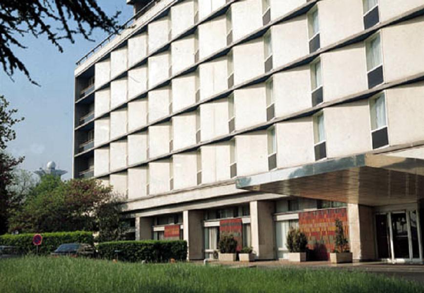
This is the sample picture the function parameters have been tuned for:
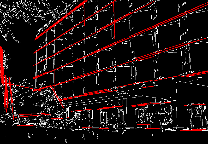
And this is the output of the above program in case of probabilistic Hough transform ("#if 0" case):
HoughCircles
Finds circles in grayscale image using Hough transform
CvSeq* cvHoughCircles( CvArr* image, void* circle_storage,
int method, double dp, double min_dist,
double param1=100, double param2=100,
int min_radius=0, int max_radius=0 );
- image
- The input 8-bit single-channel grayscale image.
- circle_storage
- The storage for the circles detected. It can be a memory storage (in this case
a sequence of circles is created in the storage and returned by the function) or single row/single column
matrix (CvMat*) of type CV_32FC3, to which the circles' parameters are written.
The matrix header is modified by the function so its
cols or rows will contain
a number of lines detected. If circle_storage is a matrix and the actual number of lines
exceeds the matrix size, the maximum possible number of circles is returned.
Every circle is encoded as 3 floating-point numbers: center coordinates (x,y) and the radius.
- method
- Currently, the only implemented method is
CV_HOUGH_GRADIENT, which is basically 21HT, described in
[Yuen03].
- dp
- Resolution of the accumulator used to detect centers of the circles. For example, if it is 1,
the accumulator will have the same resolution as the input image, if it is 2 - accumulator will have twice
smaller width and height, etc.
- min_dist
- Minimum distance between centers of the detected circles. If the parameter is too small, multiple
neighbor circles may be falsely detected in addition to a true one. If it is too large, some circles may be missed.
- param1
- The first method-specific parameter.
In case of
CV_HOUGH_GRADIENT it is the higher threshold of the two passed to Canny edge detector
(the lower one will be twice smaller).
- param2
- The second method-specific parameter.
In case of
CV_HOUGH_GRADIENT it is accumulator threshold at the center detection stage.
The smaller it is, the more false circles may be detected. Circles, corresponding to the larger accumulator
values, will be returned first.
- min_radius
- Minimal radius of the circles to search for.
- max_radius
- Maximal radius of the circles to search for.
By default the maximal radius is set to
max(image_width, image_height).
The function cvHoughCircles finds circles in grayscale image using some modification of Hough transform.
Example. Detecting circles with Hough transform.
#include <cv.h>
#include <highgui.h>
#include <math.h>
int main(int argc, char** argv)
{
IplImage* img;
if( argc == 2 && (img=cvLoadImage(argv[1], 1))!= 0)
{
IplImage* gray = cvCreateImage( cvGetSize(img), 8, 1 );
CvMemStorage* storage = cvCreateMemStorage(0);
cvCvtColor( img, gray, CV_BGR2GRAY );
cvSmooth( gray, gray, CV_GAUSSIAN, 9, 9 ); // smooth it, otherwise a lot of false circles may be detected
CvSeq* circles = cvHoughCircles( gray, storage, CV_HOUGH_GRADIENT, 2, gray->height/4, 200, 100 );
int i;
for( i = 0; i < circles->total; i++ )
{
float* p = (float*)cvGetSeqElem( circles, i );
cvCircle( img, cvPoint(cvRound(p[0]),cvRound(p[1])), 3, CV_RGB(0,255,0), -1, 8, 0 );
cvCircle( img, cvPoint(cvRound(p[0]),cvRound(p[1])), cvRound(p[2]), CV_RGB(255,0,0), 3, 8, 0 );
}
cvNamedWindow( "circles", 1 );
cvShowImage( "circles", img );
}
return 0;
}
DistTransform
Calculates distance to closest zero pixel for all non-zero pixels of source
image
void cvDistTransform( const CvArr* src, CvArr* dst, int distance_type=CV_DIST_L2,
int mask_size=3, const float* mask=NULL, CvArr* labels=NULL );
- src
- Source 8-bit single-channel (binary) image.
- dst
- Output image with calculated distances (32-bit floating-point, single-channel).
- distance_type
- Type of distance; can be
CV_DIST_L1, CV_DIST_L2, CV_DIST_C or
CV_DIST_USER.
- mask_size
- Size of distance transform mask; can be 3, 5 or 0. In case of
CV_DIST_L1 or
CV_DIST_C the parameter is forced to 3, because 3×3 mask gives the same result
as 5×5 yet it is faster. When mask_size==0, a different non-approximate algorithm
is used to calculate distances.
- mask
- User-defined mask in case of user-defined distance, it consists of 2 numbers
(horizontal/vertical shift cost, diagonal shift cost) in case of 3×3 mask and
3 numbers (horizontal/vertical shift cost, diagonal shift cost, knight’s move cost)
in case of 5×5 mask.
- labels
- The optional output 2d array of labels of integer type
and the same size as
src and dst, can now be used only with
mask_size==3 or 5.
The function cvDistTransform calculates the approximated or exact distance from every binary image pixel
to the nearest zero pixel. When mask_size==0, the function uses the accurate algorithm
[Felzenszwalb04]. When mask_size==3 or 5, the function
uses the approximate algorithm [Borgefors86].
Here is how the approximate
algorithm works. For zero pixels the function sets the zero distance. For others it finds
the shortest path to a zero pixel, consisting of basic shifts: horizontal, vertical, diagonal or knight’s move (the
latest is available for 5×5 mask). The overal distance is calculated as a sum of these basic distances.
Because the distance function should be symmetric, all the horizontal and vertical shifts must have
the same cost (that is denoted as a), all the diagonal shifts must have the same cost
(denoted b), and all knight’s moves must have the same cost (denoted c).
For CV_DIST_C and CV_DIST_L1 types the distance is calculated precisely,
whereas for CV_DIST_L2 (Euclidian distance) the distance can be calculated only with
some relative error (5×5 mask gives more accurate results), OpenCV uses the values suggested in
[Borgefors86]:
CV_DIST_C (3×3):
a=1, b=1
CV_DIST_L1 (3×3):
a=1, b=2
CV_DIST_L2 (3×3):
a=0.955, b=1.3693
CV_DIST_L2 (5×5):
a=1, b=1.4, c=2.1969
And below are samples of distance field (black (0) pixel is in the middle of white square)
in case of user-defined distance:
User-defined 3×3 mask (a=1, b=1.5)
4.5 4 3.5 3 3.5 4 4.5 4 3 2.5 2 2.5 3 4 3.5 2.5 1.5 1 1.5 2.5 3.5 3 2 1 0 1 2 3 3.5 2.5 1.5 1 1.5 2.5 3.5 4 3 2.5 2 2.5 3 4 4.5 4 3.5 3 3.5 4 4.5
User-defined 5×5 mask (a=1, b=1.5, c=2)
4.5 3.5 3 3 3 3.5 4.5 3.5 3 2 2 2 3 3.5 3 2 1.5 1 1.5 2 3 3 2 1 0 1 2 3 3 2 1.5 1 1.5 2 3 3.5 3 2 2 2 3 3.5 4 3.5 3 3 3 3.5 4
Typically, for fast coarse distance estimation CV_DIST_L2, 3×3 mask is used,
and for more accurate distance estimation CV_DIST_L2, 5×5 mask is used.
When the output parameter labels is not NULL, for every non-zero pixel
the function also finds the nearest connected component consisting of zero pixels. The connected components
themselves are found as contours in the beginning of the function.
In this mode the processing time is still O(N), where N is the number of pixels.
Thus, the function provides a very fast way to compute approximate Voronoi diagram for the binary image.
Inpaint
Inpaints the selected region in the image
void cvInpaint( const CvArr* src, const CvArr* mask, CvArr* dst,
int flags, double inpaintRadius );
- src
- The input 8-bit 1-channel or 3-channel image.
- mask
- The inpainting mask, 8-bit 1-channel image.
Non-zero pixels indicate the area that needs to be inpainted.
- dst
- The output image of the same format and the same size as input.
- flags
- The inpainting method, one of the following:
CV_INPAINT_NS - Navier-Stokes based method.
CV_INPAINT_TELEA - The method by Alexandru Telea [Telea04]
- inpaintRadius
- The radius of circlular neighborhood of each point inpainted that is considered by the algorithm.
The function cvInpaint reconstructs the selected image area from the pixel near the
area boundary. The function may be used to remove dust and scratches from a scanned photo, or
to remove undesirable objects from still images or video.
Histograms
CvHistogram
Muti-dimensional histogram
typedef struct CvHistogram
{
int type;
CvArr* bins;
float thresh[CV_MAX_DIM][2]; /* for uniform histograms */
float** thresh2; /* for non-uniform histograms */
CvMatND mat; /* embedded matrix header for array histograms */
}
CvHistogram;
CreateHist
Creates histogram
CvHistogram* cvCreateHist( int dims, int* sizes, int type,
float** ranges=NULL, int uniform=1 );
- dims
- Number of histogram dimensions.
- sizes
- Array of histogram dimension sizes.
- type
- Histogram representation format:
CV_HIST_ARRAY means that histogram data is
represented as an multi-dimensional dense array CvMatND;
CV_HIST_SPARSE means that histogram data is represented
as a multi-dimensional sparse array CvSparseMat.
- ranges
- Array of ranges for histogram bins. Its meaning depends on the
uniform parameter value.
The ranges are used for when histogram is calculated or backprojected to determine, which histogram bin
corresponds to which value/tuple of values from the input image[s].
- uniform
- Uniformity flag; if not 0, the histogram has evenly spaced bins and
for every
0<=i<cDims ranges[i] is array of two numbers: lower and upper
boundaries for the i-th histogram dimension. The whole range [lower,upper] is split then
into dims[i] equal parts to determine i-th input tuple value ranges for every histogram bin.
And if uniform=0, then i-th element of ranges array contains dims[i]+1 elements:
lower0, upper0, lower1, upper1 == lower2, ..., upperdims[i]-1,
where lowerj and upperj are lower and upper
boundaries of i-th input tuple value for j-th bin, respectively.
In either case, the input values that are beyond the specified range for a histogram bin, are not
counted by cvCalcHist and filled with 0 by cvCalcBackProject.
The function cvCreateHist creates a histogram of the specified size and returns
the pointer to the created histogram. If the array ranges is 0, the histogram
bin ranges must be specified later via The function cvSetHistBinRanges, though
cvCalcHist and cvCalcBackProject may process 8-bit images without setting
bin ranges, they assume equally spaced in 0..255 bins.
SetHistBinRanges
Sets bounds of histogram bins
void cvSetHistBinRanges( CvHistogram* hist, float** ranges, int uniform=1 );
- hist
- Histogram.
- ranges
- Array of bin ranges arrays, see cvCreateHist.
- uniform
- Uniformity flag, see cvCreateHist.
The function cvSetHistBinRanges is a stand-alone function for setting bin ranges
in the histogram. For more detailed description of the parameters ranges and
uniform see cvCalcHist function,
that can initialize the ranges as well.
Ranges for histogram bins must be set before the histogram is calculated or
backproject of the histogram is calculated.
ReleaseHist
Releases histogram
void cvReleaseHist( CvHistogram** hist );
- hist
- Double pointer to the released histogram.
The function cvReleaseHist releases the histogram (header and the data).
The pointer to histogram is cleared by the function. If *hist pointer is already
NULL, the function does nothing.
ClearHist
Clears histogram
void cvClearHist( CvHistogram* hist );
- hist
- Histogram.
The function cvClearHist sets all histogram bins to 0 in case of dense histogram and
removes all histogram bins in case of sparse array.
MakeHistHeaderForArray
Makes a histogram out of array
CvHistogram* cvMakeHistHeaderForArray( int dims, int* sizes, CvHistogram* hist,
float* data, float** ranges=NULL, int uniform=1 );
- dims
- Number of histogram dimensions.
- sizes
- Array of histogram dimension sizes.
- hist
- The histogram header initialized by the function.
- data
- Array that will be used to store histogram bins.
- ranges
- Histogram bin ranges, see cvCreateHist.
- uniform
- Uniformity flag, see cvCreateHist.
The function cvMakeHistHeaderForArray initializes the histogram, which header and
bins are allocated by user. No cvReleaseHist need to be called afterwards.
Only dense histograms can be initialized this way. The function returns hist.
QueryHistValue_*D
Queries value of histogram bin
#define cvQueryHistValue_1D( hist, idx0 ) \
cvGetReal1D( (hist)->bins, (idx0) )
#define cvQueryHistValue_2D( hist, idx0, idx1 ) \
cvGetReal2D( (hist)->bins, (idx0), (idx1) )
#define cvQueryHistValue_3D( hist, idx0, idx1, idx2 ) \
cvGetReal3D( (hist)->bins, (idx0), (idx1), (idx2) )
#define cvQueryHistValue_nD( hist, idx ) \
cvGetRealND( (hist)->bins, (idx) )
- hist
- Histogram.
- idx0, idx1, idx2, idx3
- Indices of the bin.
- idx
- Array of indices
The macros cvQueryHistValue_*D return the value of the specified bin of 1D, 2D, 3D or
N-D histogram. In case of sparse histogram the function returns 0, if the bin is not present in the
histogram, and no new bin is created.
GetHistValue_*D
Returns pointer to histogram bin
#define cvGetHistValue_1D( hist, idx0 ) \
((float*)(cvPtr1D( (hist)->bins, (idx0), 0 ))
#define cvGetHistValue_2D( hist, idx0, idx1 ) \
((float*)(cvPtr2D( (hist)->bins, (idx0), (idx1), 0 ))
#define cvGetHistValue_3D( hist, idx0, idx1, idx2 ) \
((float*)(cvPtr3D( (hist)->bins, (idx0), (idx1), (idx2), 0 ))
#define cvGetHistValue_nD( hist, idx ) \
((float*)(cvPtrND( (hist)->bins, (idx), 0 ))
- hist
- Histogram.
- idx0, idx1, idx2, idx3
- Indices of the bin.
- idx
- Array of indices
The macros cvGetHistValue_*D return pointer to the specified bin of 1D, 2D, 3D or
N-D histogram. In case of sparse histogram the function creates a new bin and sets it to 0,
unless it exists already.
GetMinMaxHistValue
Finds minimum and maximum histogram bins
void cvGetMinMaxHistValue( const CvHistogram* hist,
float* min_value, float* max_value,
int* min_idx=NULL, int* max_idx=NULL );
- hist
- Histogram.
- min_value
- Pointer to the minimum value of the histogram
- max_value
- Pointer to the maximum value of the histogram
- min_idx
- Pointer to the array of coordinates for minimum
- max_idx
- Pointer to the array of coordinates for maximum
The function cvGetMinMaxHistValue finds the minimum and maximum histogram bins and
their positions. Any of output arguments is optional.
Among several extremums with the same value the ones with minimum index (in lexicographical order)
In case of several maximums or minimums the earliest in lexicographical order
extrema locations are returned.
NormalizeHist
Normalizes histogram
void cvNormalizeHist( CvHistogram* hist, double factor );
- hist
- Pointer to the histogram.
- factor
- Normalization factor.
The function cvNormalizeHist normalizes the histogram bins by scaling them,
such that the sum of the bins becomes equal to factor.
ThreshHist
Thresholds histogram
void cvThreshHist( CvHistogram* hist, double threshold );
- hist
- Pointer to the histogram.
- threshold
- Threshold level.
The function cvThreshHist clears histogram bins
that are below the specified threshold.
CompareHist
Compares two dense histograms
double cvCompareHist( const CvHistogram* hist1, const CvHistogram* hist2, int method );
- hist1
- The first dense histogram.
- hist2
- The second dense histogram.
- method
- Comparison method, one of:
- CV_COMP_CORREL
- CV_COMP_CHISQR
- CV_COMP_INTERSECT
- CV_COMP_BHATTACHARYYA
The function cvCompareHist compares two dense histograms using
the specified method as following
(H1 denotes the first histogram, H2 - the second):
Correlation (method=CV_COMP_CORREL):
d(H1,H2)=sumI(H'1(I)•H'2(I))/sqrt(sumI[H'1(I)2]•sumI[H'2(I)2])
where
H'k(I)=Hk(I)-1/N•sumJHk(J) (N=number of histogram bins)
Chi-Square (method=CV_COMP_CHISQR):
d(H1,H2)=sumI[(H1(I)-H2(I))/(H1(I)+H2(I))]
Intersection (method=CV_COMP_INTERSECT):
d(H1,H2)=sumImin(H1(I),H2(I))
Bhattacharyya distance (method=CV_COMP_BHATTACHARYYA):
d(H1,H2)=sqrt(1-sumI(sqrt(H1(I)•H2(I))))
The function returns d(H1,H2) value.
Note: the method CV_COMP_BHATTACHARYYA only works with normalized histograms.
To compare sparse histogram or more general sparse configurations of weighted points,
consider using cvCalcEMD2 function.
CopyHist
Copies histogram
void cvCopyHist( const CvHistogram* src, CvHistogram** dst );
- src
- Source histogram.
- dst
- Pointer to destination histogram.
The function cvCopyHist makes a copy of the histogram. If the second histogram
pointer *dst is NULL, a new histogram of the same size as src is created.
Otherwise, both histograms must have equal types and sizes.
Then the function copies the source histogram bins values to destination histogram and
sets the same bin values ranges as in src.
CalcHist
Calculates histogram of image(s)
void cvCalcHist( IplImage** image, CvHistogram* hist,
int accumulate=0, const CvArr* mask=NULL );
- image
- Source images (though, you may pass CvMat** as well), all are of the same size and type
- hist
- Pointer to the histogram.
- accumulate
- Accumulation flag. If it is set, the histogram is not cleared in the beginning.
This feature allows user to compute a single histogram from several images, or to update the histogram online.
- mask
- The operation mask, determines what pixels of the source images are counted.
The function cvCalcHist calculates the histogram of one or more single-channel images.
The elements of a tuple that is used to increment a histogram bin are taken at the same
location from the corresponding input images.
Sample. Calculating and displaying 2D Hue-Saturation histogram of a color image
#include <cv.h>
#include <highgui.h>
int main( int argc, char** argv )
{
IplImage* src;
if( argc == 2 && (src=cvLoadImage(argv[1], 1))!= 0)
{
IplImage* h_plane = cvCreateImage( cvGetSize(src), 8, 1 );
IplImage* s_plane = cvCreateImage( cvGetSize(src), 8, 1 );
IplImage* v_plane = cvCreateImage( cvGetSize(src), 8, 1 );
IplImage* planes[] = { h_plane, s_plane };
IplImage* hsv = cvCreateImage( cvGetSize(src), 8, 3 );
int h_bins = 30, s_bins = 32;
int hist_size[] = {h_bins, s_bins};
float h_ranges[] = { 0, 180 }; /* hue varies from 0 (~0°red) to 180 (~360°red again) */
float s_ranges[] = { 0, 255 }; /* saturation varies from 0 (black-gray-white) to 255 (pure spectrum color) */
float* ranges[] = { h_ranges, s_ranges };
int scale = 10;
IplImage* hist_img = cvCreateImage( cvSize(h_bins*scale,s_bins*scale), 8, 3 );
CvHistogram* hist;
float max_value = 0;
int h, s;
cvCvtColor( src, hsv, CV_BGR2HSV );
cvCvtPixToPlane( hsv, h_plane, s_plane, v_plane, 0 );
hist = cvCreateHist( 2, hist_size, CV_HIST_ARRAY, ranges, 1 );
cvCalcHist( planes, hist, 0, 0 );
cvGetMinMaxHistValue( hist, 0, &max_value, 0, 0 );
cvZero( hist_img );
for( h = 0; h < h_bins; h++ )
{
for( s = 0; s < s_bins; s++ )
{
float bin_val = cvQueryHistValue_2D( hist, h, s );
int intensity = cvRound(bin_val*255/max_value);
cvRectangle( hist_img, cvPoint( h*scale, s*scale ),
cvPoint( (h+1)*scale - 1, (s+1)*scale - 1),
CV_RGB(intensity,intensity,intensity), /* graw a grayscale histogram.
if you have idea how to do it
nicer let us know */
CV_FILLED );
}
}
cvNamedWindow( "Source", 1 );
cvShowImage( "Source", src );
cvNamedWindow( "H-S Histogram", 1 );
cvShowImage( "H-S Histogram", hist_img );
cvWaitKey(0);
}
}
CalcBackProject
Calculates back projection
void cvCalcBackProject( IplImage** image, CvArr* back_project, const CvHistogram* hist );
- image
- Source images (though you may pass CvMat** as well), all are of the same size and type
- back_project
- Destination back projection image of the same type as the source images.
- hist
- Histogram.
The function cvCalcBackProject calculates the back project of the histogram. For
each tuple of pixels at the same position of all input single-channel
images the function puts the value of the histogram bin, corresponding to the tuple,
to the destination image. In terms of statistics, the value of each output image pixel
is probability of the observed tuple given the distribution (histogram).
For example, to find a red object in the picture, one may do the following:
- Calculate a hue histogram for the red object assuming the image contains only
this object. The histogram is likely to have a strong maximum, corresponding
to red color.
- Calculate back projection of a hue plane of input image where the object is searched,
using the histogram. Threshold the image.
- Find connected components in the resulting picture and choose the right
component using some additional criteria, for example, the largest connected
component.
That is the approximate algorithm of Camshift color object tracker, except for the 3rd step,
instead of which CAMSHIFT algorithm is used to locate the object on the back projection given
the previous object position.
CalcBackProjectPatch
Locates a template within image by histogram comparison
void cvCalcBackProjectPatch( IplImage** images, CvArr* dst,
CvSize patch_size, CvHistogram* hist,
int method, float factor );
- images
- Source images (though, you may pass CvMat** as well), all of the same size
- dst
- Destination image.
- patch_size
- Size of patch slid though the source images.
- hist
- Histogram
- method
- Compasion method, passed to cvCompareHist (see description of that function).
- factor
- Normalization factor for histograms,
will affect normalization scale of destination image, pass 1. if unsure.
The function cvCalcBackProjectPatch compares histogram, computed over
each possible rectangular patch of the specfied size in the input images,
and stores the results to the output map dst.
In pseudo-code the operation may be written as:
for (x,y) in images (until (x+patch_size.width-1,y+patch_size.height-1) is inside the images) do
compute histogram over the ROI (x,y,x+patch_size.width,y+patch_size.height) in images
(see cvCalcHist)
normalize the histogram using the factor
(see cvNormalizeHist)
compare the normalized histogram with input histogram hist using the specified method
(see cvCompareHist)
store the result to dst(x,y)
end for
See also a similar function cvMatchTemplate.
Back Project Calculation by Patches
CalcProbDensity
Divides one histogram by another
void cvCalcProbDensity( const CvHistogram* hist1, const CvHistogram* hist2,
CvHistogram* dst_hist, double scale=255 );
- hist1
- first histogram (the divisor).
- hist2
- second histogram.
- dst_hist
- destination histogram.
- scale
- scale factor for the destination histogram.
The function cvCalcProbDensity calculates the object probability density from
the two histograms as:
dist_hist(I)=0 if hist1(I)==0
scale if hist1(I)!=0 && hist2(I)>hist1(I)
hist2(I)*scale/hist1(I) if hist1(I)!=0 && hist2(I)<=hist1(I)
So the destination histogram bins are within less than scale.
EqualizeHist
Equalizes histogram of grayscale image
void cvEqualizeHist( const CvArr* src, CvArr* dst );
- src
- The input 8-bit single-channel image.
- dst
- The output image of the same size and the same data type as
src.
The function cvEqualizeHist equalizes histogram of the input image
using the following algorithm:
1. calculate histogram H for src.
2. normalize histogram, so that the sum of histogram bins is 255.
3. compute integral of the histogram:
H’(i) = sum0≤j≤iH(j)
4. transform the image using H’ as a look-up table: dst(x,y)=H’(src(x,y))
The algorithm normalizes brightness and increases contrast of the image.
Matching
MatchTemplate
Compares template against overlapped image regions
void cvMatchTemplate( const CvArr* image, const CvArr* templ,
CvArr* result, int method );
- image
- Image where the search is running.
It should be 8-bit or 32-bit floating-point.
- templ
- Searched template; must be not greater than the source image and the same data type as the image.
- result
- A map of comparison results; single-channel 32-bit floating-point. If
image is
W×H and templ is w×h then result must
be W-w+1×H-h+1.
- method
- Specifies the way the template must be compared with image regions (see below).
The function cvMatchTemplate is similiar to cvCalcBackProjectPatch.
It slids through image, compares overlapped patches of size w×h
with templ using the specified method and stores the comparison results
to result. Here are the formulae for the different comparison methods one may use
(I denotes image, T - template, R - result.
The summation is done over template and/or the image patch: x'=0..w-1, y'=0..h-1):
method=CV_TM_SQDIFF:
R(x,y)=sumx',y'[T(x',y')-I(x+x',y+y')]2
method=CV_TM_SQDIFF_NORMED:
R(x,y)=sumx',y'[T(x',y')-I(x+x',y+y')]2/sqrt[sumx',y'T(x',y')2•sumx',y'I(x+x',y+y')2]
method=CV_TM_CCORR:
R(x,y)=sumx',y'[T(x',y')•I(x+x',y+y')]
method=CV_TM_CCORR_NORMED:
R(x,y)=sumx',y'[T(x',y')•I(x+x',y+y')]/sqrt[sumx',y'T(x',y')2•sumx',y'I(x+x',y+y')2]
method=CV_TM_CCOEFF:
R(x,y)=sumx',y'[T'(x',y')•I'(x+x',y+y')],
where T'(x',y')=T(x',y') - 1/(w•h)•sumx",y"T(x",y")
I'(x+x',y+y')=I(x+x',y+y') - 1/(w•h)•sumx",y"I(x+x",y+y")
method=CV_TM_CCOEFF_NORMED:
R(x,y)=sumx',y'[T'(x',y')•I'(x+x',y+y')]/sqrt[sumx',y'T'(x',y')2•sumx',y'I'(x+x',y+y')2]
After the function finishes comparison, the best matches can be found as global minimums (CV_TM_SQDIFF*)
or maximums (CV_TM_CCORR* and CV_TM_CCOEFF*) using cvMinMaxLoc function.
In case of color image and template summation in both numerator and each sum in denominator is done
over all the channels (and separate mean values are used for each channel).
MatchShapes
Compares two shapes
double cvMatchShapes( const void* object1, const void* object2,
int method, double parameter=0 );
- object1
- First contour or grayscale image
- object2
- Second contour or grayscale image
- method
- Comparison method, one of CV_CONTOUR_MATCH_I1, CV_CONTOURS_MATCH_I2 or CV_CONTOURS_MATCH_I3.
- parameter
- Method-specific parameter (is not used now).
The function cvMatchShapes compares two shapes. The 3 implemented methods all
use Hu moments (see cvGetHuMoments)
(A ~ object1, B - object2):
method=CV_CONTOUR_MATCH_I1:
I1(A,B)=sumi=1..7abs(1/mAi - 1/mBi)
method=CV_CONTOUR_MATCH_I2:
I2(A,B)=sumi=1..7abs(mAi - mBi)
method=CV_CONTOUR_MATCH_I3:
I3(A,B)=sumi=1..7abs(mAi - mBi)/abs(mAi)
where
mAi=sign(hAi)•log(hAi),
mBi=sign(hBi)•log(hBi),
hAi, hBi - Hu moments of A and B, respectively.
CalcEMD2
Computes "minimal work" distance between two weighted point configurations
float cvCalcEMD2( const CvArr* signature1, const CvArr* signature2, int distance_type,
CvDistanceFunction distance_func=NULL, const CvArr* cost_matrix=NULL,
CvArr* flow=NULL, float* lower_bound=NULL, void* userdata=NULL );
typedef float (*CvDistanceFunction)(const float* f1, const float* f2, void* userdata);
- signature1
- First signature,
size1×dims+1 floating-point matrix.
Each row stores the point weight followed by the point coordinates. The matrix is allowed to
have a single column (weights only) if the user-defined cost matrix is used.
- signature2
- Second signature of the same format as
signature1, though the number
of rows may be different. The total weights may be different, in this case an extra "dummy" point
is added to either signature1 or signature2.
- distance_type
- Metrics used;
CV_DIST_L1, CV_DIST_L2, and CV_DIST_C stand for one of
the standard metrics; CV_DIST_USER means that a user-defined function distance_func or
pre-calculated cost_matrix is used.
- distance_func
- The user-defined distance function.
It takes coordinates of two points and returns the distance between the points.
- cost_matrix
- The user-defined
size1×size2 cost matrix.
At least one of cost_matrix and distance_func must be NULL.
Also, if a cost matrix is used, lower boundary (see below) can not be calculated,
because it needs a metric function.
- flow
- The resultant
size1×size2 flow matrix: flowij is a flow
from i-th point of signature1 to j-th point of signature2
- lower_bound
- Optional input/output parameter: lower boundary of distance between the two signatures that
is a distance between mass centers. The lower boundary may not be calculated if
the user-defined cost matrix is used, the total weights of point configurations are
not equal, or there is the signatures consist of weights only
(i.e. the signature matrices have a single column).
User must initialize
*lower_bound.
If the calculated distance between mass centers is greater or equal to *lower_bound
(it means that the signatures are far enough) the function does not calculate EMD.
In any case *lower_bound is set to the calculated distance between mass centers
on return. Thus, if user wants to calculate both distance between mass centers and EMD,
*lower_bound should be set to 0.
- userdata
- Pointer to optional data that is passed into the user-defined distance function.
The function cvCalcEMD2 computes earth mover distance and/or a lower boundary of
the distance between the two weighted point configurations.
One of the application desctibed in [RubnerSept98] is multi-dimensional
histogram comparison for image retrieval.
EMD is a transportation problem that is solved using some modification of simplex algorithm,
thus the complexity is exponential in the worst case, though, it is much faster in average.
In case of a real metric the lower boundary can be calculated even faster (using linear-time algorithm)
and it can be used to determine roughly whether the two
signatures are far enough so that they cannot relate to the same object.
Structural Analysis
Contour Processing Functions
ApproxChains
Approximates Freeman chain(s) with polygonal curve
CvSeq* cvApproxChains( CvSeq* src_seq, CvMemStorage* storage,
int method=CV_CHAIN_APPROX_SIMPLE,
double parameter=0, int minimal_perimeter=0, int recursive=0 );
- src_seq
- Pointer to the chain that can refer to other chains.
- storage
- Storage location for the resulting polylines.
- method
- Approximation method (see the description of the function
cvFindContours).
- parameter
- Method parameter (not used now).
- minimal_perimeter
- Approximates only those contours whose perimeters are not less
than
minimal_perimeter. Other chains are removed from the resulting structure.
- recursive
- If not 0, the function approximates all chains that access can be
obtained to from
src_seq by h_next or v_next links. If 0, the single chain is
approximated.
This is a stand-alone approximation routine. The function cvApproxChains works
exactly in the same way as cvFindContours with the corresponding approximation flag.
The function returns pointer to the first resultant contour.
Other approximated contours, if any, can be accessed via v_next or
h_next fields of the returned structure.
StartReadChainPoints
Initializes chain reader
void cvStartReadChainPoints( CvChain* chain, CvChainPtReader* reader );
chain Pointer to chain.
reader Chain reader state.
The function cvStartReadChainPoints initializes a special reader
(see Dynamic Data Structures
for more information on sets and sequences).
ReadChainPoint
Gets next chain point
CvPoint cvReadChainPoint( CvChainPtReader* reader );
- reader
- Chain reader state.
The function cvReadChainPoint returns the current chain point and updates the reader position.
ApproxPoly
Approximates polygonal curve(s) with desired precision
CvSeq* cvApproxPoly( const void* src_seq, int header_size, CvMemStorage* storage,
int method, double parameter, int parameter2=0 );
- src_seq
- Sequence of array of points.
- header_size
- Header size of approximated curve[s].
- storage
- Container for approximated contours. If it is NULL, the input sequences' storage is used.
- method
- Approximation method; only
CV_POLY_APPROX_DP is supported, that
corresponds to Douglas-Peucker algorithm.
- parameter
- Method-specific parameter; in case of
CV_POLY_APPROX_DP it is a desired approximation accuracy.
- parameter2
- If case if
src_seq is sequence it means whether the single sequence should
be approximated or all sequences on the same level or below src_seq (see cvFindContours for
description of hierarchical contour structures). And if src_seq is array (CvMat*) of
points, the parameter specifies whether the curve is closed (parameter2!=0) or
not (parameter2=0).
The function cvApproxPoly approximates one or more curves and returns the approximation
result[s]. In case of multiple curves approximation the resultant tree will have the same structure as
the input one (1:1 correspondence).
BoundingRect
Calculates up-right bounding rectangle of point set
CvRect cvBoundingRect( CvArr* points, int update=0 );
- points
- Either a 2D point set, represented as a sequence (
CvSeq*, CvContour*)
or vector (CvMat*) of points,
or 8-bit single-channel mask image (CvMat*, IplImage*),
in which non-zero pixels are considered.
- update
- The update flag. Here is list of possible combination of the flag values and type of
contour:
points is CvContour*, update=0: the bounding rectangle is not calculated, but it is read from rect field of the contour header.
points is CvContour*, update=1: the bounding rectangle is calculated and written to rect field of the contour header.
For example, this mode is used by cvFindContours.
points is CvSeq* or CvMat*: update is ignored,
the bounding rectangle is calculated and returned.
The function cvBoundingRect returns the up-right bounding rectangle for 2d point set.
ContourArea
Calculates area of the whole contour or contour section
double cvContourArea( const CvArr* contour, CvSlice slice=CV_WHOLE_SEQ );
- contour
- Contour (sequence or array of vertices).
- slice
- Starting and ending points of the contour section of interest, by default area of the whole
contour is calculated.
The function cvContourArea calculates area of the whole contour or contour section. In the latter
case the total area bounded by the contour arc and the chord connecting the 2 selected points is calculated as
shown on the picture below:
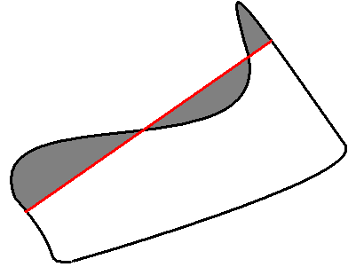
NOTE: Orientation of the contour affects the area sign, thus the function may return
negative result. Use fabs() function from C runtime to get the absolute value of
area.
ArcLength
Calculates contour perimeter or curve length
double cvArcLength( const void* curve, CvSlice slice=CV_WHOLE_SEQ, int is_closed=-1 );
- curve
- Sequence or array of the curve points.
- slice
- Starting and ending points of the curve, by default the whole curve length is
calculated.
- is_closed
- Indicates whether the curve is closed or not. There are 3 cases:
- is_closed=0 - the curve is assumed to be unclosed.
- is_closed>0 - the curve is assumed to be closed.
- is_closed<0 - if curve is sequence, the flag CV_SEQ_FLAG_CLOSED of
((CvSeq*)curve)->flags is checked to determine if the curve is closed or not,
otherwise (curve is represented by array (CvMat*) of points) it is assumed
to be unclosed.
The function cvArcLength calculates length or curve as sum of lengths of segments
between subsequent points
CreateContourTree
Creates hierarchical representation of contour
CvContourTree* cvCreateContourTree( const CvSeq* contour, CvMemStorage* storage, double threshold );
- contour
- Input contour.
- storage
- Container for output tree.
- threshold
- Approximation accuracy.
The function cvCreateContourTree creates binary tree representation for the input
contour and returns the pointer to its root. If the parameter threshold
is less than or equal to 0, the function creates full binary tree
representation. If the threshold is greater than 0, the function creates
representation with the precision threshold: if the vertices with the
interceptive area of its base line are less than threshold, the tree should not
be built any further. The function returns the created tree.
ContourFromContourTree
Restores contour from tree
CvSeq* cvContourFromContourTree( const CvContourTree* tree, CvMemStorage* storage,
CvTermCriteria criteria );
- tree
- Contour tree.
- storage
- Container for the reconstructed contour.
- criteria
- Criteria, where to stop reconstruction.
The function cvContourFromContourTree restores the contour from its binary tree
representation. The parameter criteria determines the accuracy and/or the
number of tree levels used for reconstruction, so it is possible to build approximated contour.
The function returns reconstructed contour.
MatchContourTrees
Compares two contours using their tree representations
double cvMatchContourTrees( const CvContourTree* tree1, const CvContourTree* tree2,
int method, double threshold );
- tree1
- First contour tree.
- tree2
- Second contour tree.
- method
- Similarity measure, only
CV_CONTOUR_TREES_MATCH_I1 is supported.
- threshold
- Similarity threshold.
The function cvMatchContourTrees calculates the value of the matching measure for
two contour trees. The similarity measure is calculated level by level from the
binary tree roots. If at the certain level difference between contours becomes less than threshold,
the reconstruction process is interrupted and the current difference is returned.
Computational Geometry
MaxRect
Finds bounding rectangle for two given rectangles
CvRect cvMaxRect( const CvRect* rect1, const CvRect* rect2 );
- rect1
- First rectangle
- rect2
- Second rectangle
The function cvMaxRect finds minimum area rectangle that contains both input rectangles inside:
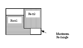
CvBox2D
Rotated 2D box
typedef struct CvBox2D
{
CvPoint2D32f center; /* center of the box */
CvSize2D32f size; /* box width and length */
float angle; /* angle between the horizontal axis
and the first side (i.e. length) in degrees */
}
CvBox2D;
PointSeqFromMat
Initializes point sequence header from a point vector
CvSeq* cvPointSeqFromMat( int seq_kind, const CvArr* mat,
CvContour* contour_header,
CvSeqBlock* block );
- seq_kind
- Type of the point sequence: point set (0), a curve (
CV_SEQ_KIND_CURVE),
closed curve (CV_SEQ_KIND_CURVE+CV_SEQ_FLAG_CLOSED) etc.
- mat
- Input matrix. It should be continuous 1-dimensional vector of points, that is, it should have
type
CV_32SC2 or CV_32FC2.
- contour_header
- Contour header, initialized by the function.
- block
- Sequence block header, initialized by the function.
The function cvPointSeqFromMat initializes sequence header to create a "virtual" sequence which
elements reside in the specified matrix. No data is copied. The initialized sequence header may be passed to
any function that takes a point sequence on input. No extra elements could be added to the sequence,
but some may be removed. The function is a specialized variant of
cvMakeSeqHeaderForArray and uses the latter internally.
It returns pointer to the initialized contour header. Note that the bounding rectangle (field rect of
CvContour strucuture is not initialized by the function. If you need one, use
cvBoundingRect.
Here is the simple usage example.
CvContour header;
CvSeqBlock block;
CvMat* vector = cvCreateMat( 1, 3, CV_32SC2 );
CV_MAT_ELEM( *vector, CvPoint, 0, 0 ) = cvPoint(100,100);
CV_MAT_ELEM( *vector, CvPoint, 0, 1 ) = cvPoint(100,200);
CV_MAT_ELEM( *vector, CvPoint, 0, 2 ) = cvPoint(200,100);
IplImage* img = cvCreateImage( cvSize(300,300), 8, 3 );
cvZero(img);
cvDrawContours( img, cvPointSeqFromMat(CV_SEQ_KIND_CURVE+CV_SEQ_FLAG_CLOSED,
vector, &header, &block), CV_RGB(255,0,0), CV_RGB(255,0,0), 0, 3, 8, cvPoint(0,0));
BoxPoints
Finds box vertices
void cvBoxPoints( CvBox2D box, CvPoint2D32f pt[4] );
- box
- Box
- pt
- Array of vertices
The function cvBoxPoints calculates vertices of the input 2d box.
Here is the function code:
void cvBoxPoints( CvBox2D box, CvPoint2D32f pt[4] )
{
double angle = box.angle*CV_PI/180.
float a = (float)cos(angle)*0.5f;
float b = (float)sin(angle)*0.5f;
pt[0].x = box.center.x - a*box.size.height - b*box.size.width;
pt[0].y = box.center.y + b*box.size.height - a*box.size.width;
pt[1].x = box.center.x + a*box.size.height - b*box.size.width;
pt[1].y = box.center.y - b*box.size.height - a*box.size.width;
pt[2].x = 2*box.center.x - pt[0].x;
pt[2].y = 2*box.center.y - pt[0].y;
pt[3].x = 2*box.center.x - pt[1].x;
pt[3].y = 2*box.center.y - pt[1].y;
}
FitEllipse
Fits ellipse to set of 2D points
CvBox2D cvFitEllipse2( const CvArr* points );
- points
- Sequence or array of points.
The function cvFitEllipse calculates ellipse that fits best (in least-squares sense)
to a set of 2D points. The meaning of the returned structure fields is similar to those
in cvEllipse except that size stores the full lengths of the ellipse axises,
not half-lengths
FitLine
Fits line to 2D or 3D point set
void cvFitLine( const CvArr* points, int dist_type, double param,
double reps, double aeps, float* line );
- points
- Sequence or array of 2D or 3D points with 32-bit integer or floating-point coordinates.
- dist_type
- The distance used for fitting (see the discussion).
- param
- Numerical parameter (
C) for some types of distances, if 0 then some optimal value is chosen.
- reps, aeps
- Sufficient accuracy for radius (distance between the coordinate origin and the line)
and angle, respectively, 0.01 would be a good defaults for both.
- line
- The output line parameters. In case of 2d fitting it is array of 4 floats
(vx, vy, x0, y0)
where (vx, vy) is a normalized vector collinear to the line and (x0, y0) is some point on the line.
In case of 3D fitting it is array of 6 floats (vx, vy, vz, x0, y0, z0)
where (vx, vy, vz) is a normalized vector collinear to the line and (x0, y0, z0) is some point on the line.
The function cvFitLine fits line to 2D or 3D point set by minimizing sumiρ(ri),
where ri is distance between i-th point and the line and ρ(r) is a distance function, one of:
dist_type=CV_DIST_L2 (L2):
ρ(r)=r2/2 (the simplest and the fastest least-squares method)
dist_type=CV_DIST_L1 (L1):
ρ(r)=r
dist_type=CV_DIST_L12 (L1-L2):
ρ(r)=2•[sqrt(1+r2/2) - 1]
dist_type=CV_DIST_FAIR (Fair):
ρ(r)=C2•[r/C - log(1 + r/C)], C=1.3998
dist_type=CV_DIST_WELSCH (Welsch):
ρ(r)=C2/2•[1 - exp(-(r/C)2)], C=2.9846
dist_type=CV_DIST_HUBER (Huber):
ρ(r)= r2/2, if r < C
C•(r-C/2), otherwise; C=1.345
ConvexHull2
Finds convex hull of point set
CvSeq* cvConvexHull2( const CvArr* input, void* hull_storage=NULL,
int orientation=CV_CLOCKWISE, int return_points=0 );
- points
- Sequence or array of 2D points with 32-bit integer or floating-point coordinates.
- hull_storage
- The destination array (CvMat*) or memory storage (CvMemStorage*) that will store the convex hull.
If it is array, it should be 1d and have the same number of elements as the input array/sequence.
On output the header is modified so to truncate the array downto the hull size.
- orientation
- Desired orientation of convex hull:
CV_CLOCKWISE or CV_COUNTER_CLOCKWISE.
- return_points
- If non-zero, the points themselves will be stored
in the hull instead of indices if
hull_storage is array, or pointers if hull_storage is memory storage.
The function cvConvexHull2 finds convex hull of 2D point set using Sklansky’s algorithm.
If hull_storage is memory storage, the function creates a sequence containing the hull points or
pointers to them, depending on return_points value and returns the sequence on output.
Example. Building convex hull for a sequence or array of points
#include "cv.h"
#include "highgui.h"
#include <stdlib.h>
#define ARRAY 0 /* switch between array/sequence method by replacing 0<=>1 */
void main( int argc, char** argv )
{
IplImage* img = cvCreateImage( cvSize( 500, 500 ), 8, 3 );
cvNamedWindow( "hull", 1 );
#if !ARRAY
CvMemStorage* storage = cvCreateMemStorage();
#endif
for(;;)
{
int i, count = rand()%100 + 1, hullcount;
CvPoint pt0;
#if !ARRAY
CvSeq* ptseq = cvCreateSeq( CV_SEQ_KIND_GENERIC|CV_32SC2, sizeof(CvContour),
sizeof(CvPoint), storage );
CvSeq* hull;
for( i = 0; i < count; i++ )
{
pt0.x = rand() % (img->width/2) + img->width/4;
pt0.y = rand() % (img->height/2) + img->height/4;
cvSeqPush( ptseq, &pt0 );
}
hull = cvConvexHull2( ptseq, 0, CV_CLOCKWISE, 0 );
hullcount = hull->total;
#else
CvPoint* points = (CvPoint*)malloc( count * sizeof(points[0]));
int* hull = (int*)malloc( count * sizeof(hull[0]));
CvMat point_mat = cvMat( 1, count, CV_32SC2, points );
CvMat hull_mat = cvMat( 1, count, CV_32SC1, hull );
for( i = 0; i < count; i++ )
{
pt0.x = rand() % (img->width/2) + img->width/4;
pt0.y = rand() % (img->height/2) + img->height/4;
points[i] = pt0;
}
cvConvexHull2( &point_mat, &hull_mat, CV_CLOCKWISE, 0 );
hullcount = hull_mat.cols;
#endif
cvZero( img );
for( i = 0; i < count; i++ )
{
#if !ARRAY
pt0 = *CV_GET_SEQ_ELEM( CvPoint, ptseq, i );
#else
pt0 = points[i];
#endif
cvCircle( img, pt0, 2, CV_RGB( 255, 0, 0 ), CV_FILLED );
}
#if !ARRAY
pt0 = **CV_GET_SEQ_ELEM( CvPoint*, hull, hullcount - 1 );
#else
pt0 = points[hull[hullcount-1]];
#endif
for( i = 0; i < hullcount; i++ )
{
#if !ARRAY
CvPoint pt = **CV_GET_SEQ_ELEM( CvPoint*, hull, i );
#else
CvPoint pt = points[hull[i]];
#endif
cvLine( img, pt0, pt, CV_RGB( 0, 255, 0 ));
pt0 = pt;
}
cvShowImage( "hull", img );
int key = cvWaitKey(0);
if( key == 27 ) // 'ESC'
break;
#if !ARRAY
cvClearMemStorage( storage );
#else
free( points );
free( hull );
#endif
}
}
CheckContourConvexity
Tests contour convex
int cvCheckContourConvexity( const CvArr* contour );
- contour
- Tested contour (sequence or array of points).
The function cvCheckContourConvexity tests whether the input contour is convex or not.
The contour must be simple, i.e. without self-intersections.
CvConvexityDefect
Structure describing a single contour convexity detect
typedef struct CvConvexityDefect
{
CvPoint* start; /* point of the contour where the defect begins */
CvPoint* end; /* point of the contour where the defect ends */
CvPoint* depth_point; /* the farthest from the convex hull point within the defect */
float depth; /* distance between the farthest point and the convex hull */
} CvConvexityDefect;
Picture. Convexity defects of hand contour.
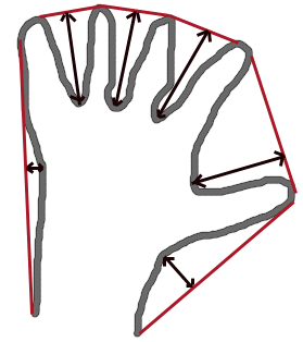
ConvexityDefects
Finds convexity defects of contour
CvSeq* cvConvexityDefects( const CvArr* contour, const CvArr* convexhull,
CvMemStorage* storage=NULL );
- contour
- Input contour.
- convexhull
- Convex hull obtained using cvConvexHull2 that should contain pointers or indices
to the contour points, not the hull points themselves, i.e.
return_points parameter in cvConvexHull2
should be 0.
- storage
- Container for output sequence of convexity defects. If it is NULL, contour or hull
(in that order) storage is used.
The function cvConvexityDefects finds all convexity defects of the input contour
and returns a sequence of the CvConvexityDefect structures.
PointPolygonTest
Point in contour test
double cvPointPolygonTest( const CvArr* contour,
CvPoint2D32f pt, int measure_dist );
- contour
- Input contour.
- pt
- The point tested against the contour.
- measure_dist
- If it is non-zero, the function estimates distance from the point to the nearest contour edge.
The function cvPointPolygonTest determines whether the point is inside contour, outside, or lies
on an edge (or coinsides with a vertex). It returns positive, negative or zero value, correspondingly.
When measure_dist=0, the return value is +1, -1 and 0, respectively.
When measure_dist≠0, it is a signed distance between the point and the nearest contour edge.
Here is the sample output of the function, where each image pixel is tested against the contour.
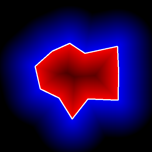
MinAreaRect2
Finds circumscribed rectangle of minimal area for given 2D point set
CvBox2D cvMinAreaRect2( const CvArr* points, CvMemStorage* storage=NULL );
- points
- Sequence or array of points.
- storage
- Optional temporary memory storage.
The function cvMinAreaRect2 finds a circumscribed rectangle of the minimal area for 2D point set
by building convex hull for the set and applying rotating calipers technique to the hull.
Picture. Minimal-area bounding rectangle for contour
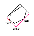
MinEnclosingCircle
Finds circumscribed circle of minimal area for given 2D point set
int cvMinEnclosingCircle( const CvArr* points, CvPoint2D32f* center, float* radius );
- points
- Sequence or array of 2D points.
- center
- Output parameter. The center of the enclosing circle.
- radius
- Output parameter. The radius of the enclosing circle.
The function cvMinEnclosingCircle finds the minimal circumscribed circle for
2D point set using iterative algorithm. It returns nonzero if the resultant circle contains all the
input points and zero otherwise (i.e. algorithm failed).
CalcPGH
Calculates pair-wise geometrical histogram for contour
void cvCalcPGH( const CvSeq* contour, CvHistogram* hist );
- contour
- Input contour. Currently, only integer point coordinates are allowed.
- hist
- Calculated histogram; must be two-dimensional.
The function cvCalcPGH calculates 2D pair-wise geometrical histogram (PGH), described in
[Iivarinen97], for the contour.
The algorithm considers every pair of the contour edges. The angle
between the edges and the minimum/maximum distances are determined for every
pair. To do this each of the edges in turn is taken as the base, while the
function loops through all the other edges. When the base edge and any other
edge are considered, the minimum and maximum distances from the points on the
non-base edge and line of the base edge are selected. The angle between the
edges defines the row of the histogram in which all the bins that correspond to
the distance between the calculated minimum and maximum distances are
incremented (that is, the histogram is transposed relatively to [Iivarninen97] definition).
The histogram can be used for contour matching.
Planar Subdivisions
CvSubdiv2D
Planar subdivision
#define CV_SUBDIV2D_FIELDS() \
CV_GRAPH_FIELDS() \
int quad_edges; \
int is_geometry_valid; \
CvSubdiv2DEdge recent_edge; \
CvPoint2D32f topleft; \
CvPoint2D32f bottomright;
typedef struct CvSubdiv2D
{
CV_SUBDIV2D_FIELDS()
}
CvSubdiv2D;
Planar subdivision is a subdivision of a plane into a set of non-overlapped regions (facets) that
cover the whole plane. The above structure describes a subdivision built on 2d point set, where
the points are linked together and form a planar graph, which, together with a few edges connecting
exterior subdivision points (namely, convex hull points) with infinity, subdivides a plane into facets
by its edges.
For every subdivision there exists dual subdivision there facets and points (subdivision vertices)
swap their roles, that is, a facet is treated as a vertex (called virtual point below) of dual subdivision
and the original subdivision vertices become facets. On the picture below original subdivision is marked with solid lines
and dual subdivision with dot lines
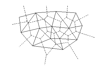
OpenCV subdivides plane into triangles using Delaunay’s algorithm.
Subdivision is built iteratively starting from a dummy triangle that includes
all the subdivision points for sure.
In this case the dual subdivision is Voronoi diagram of input 2d point set.
The subdivisions can be used for 3d piece-wise transformation of a plane, morphing, fast location of
points on the plane, building special graphs (such as NNG,RNG) etc.
CvQuadEdge2D
Quad-edge of planar subdivision
/* one of edges within quad-edge, lower 2 bits is index (0..3)
and upper bits are quad-edge pointer */
typedef long CvSubdiv2DEdge;
/* quad-edge structure fields */
#define CV_QUADEDGE2D_FIELDS() \
int flags; \
struct CvSubdiv2DPoint* pt[4]; \
CvSubdiv2DEdge next[4];
typedef struct CvQuadEdge2D
{
CV_QUADEDGE2D_FIELDS()
}
CvQuadEdge2D;
Quad-edge is a basic element of subdivision, it contains four edges (e, eRot (in red) and reversed e & eRot (in green)):
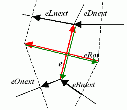
CvSubdiv2DPoint
Point of original or dual subdivision
#define CV_SUBDIV2D_POINT_FIELDS()\
int flags; \
CvSubdiv2DEdge first; \
CvPoint2D32f pt;
#define CV_SUBDIV2D_VIRTUAL_POINT_FLAG (1 << 30)
typedef struct CvSubdiv2DPoint
{
CV_SUBDIV2D_POINT_FIELDS()
}
CvSubdiv2DPoint;
Subdiv2DGetEdge
Returns one of edges related to given
CvSubdiv2DEdge cvSubdiv2DGetEdge( CvSubdiv2DEdge edge, CvNextEdgeType type );
#define cvSubdiv2DNextEdge( edge ) cvSubdiv2DGetEdge( edge, CV_NEXT_AROUND_ORG )
- edge
- Subdivision edge (not a quad-edge)
- type
- Specifies, which of related edges to return, one of:
- CV_NEXT_AROUND_ORG - next around the edge origin (
eOnext on the picture above if e is the input edge)
- CV_NEXT_AROUND_DST - next around the edge vertex (
eDnext)
- CV_PREV_AROUND_ORG - previous around the edge origin (reversed
eRnext)
- CV_PREV_AROUND_DST - previous around the edge destination (reversed
eLnext)
- CV_NEXT_AROUND_LEFT - next around the left facet (
eLnext)
- CV_NEXT_AROUND_RIGHT - next around the right facet (
eRnext)
- CV_PREV_AROUND_LEFT - previous around the left facet (reversed
eOnext)
- CV_PREV_AROUND_RIGHT - previous around the right facet (reversed
eDnext)
The function cvSubdiv2DGetEdge returns one the edges related to the input edge.
Subdiv2DRotateEdge
Returns another edge of the same quad-edge
CvSubdiv2DEdge cvSubdiv2DRotateEdge( CvSubdiv2DEdge edge, int rotate );
- edge
- Subdivision edge (not a quad-edge)
- type
- Specifies, which of edges of the same quad-edge as the input one to return, one of:
- 0 - the input edge (
e on the picture above if e is the input edge)
- 1 - the rotated edge (
eRot)
- 2 - the reversed edge (reversed
e (in green))
- 3 - the reversed rotated edge (reversed
eRot (in green))
The function cvSubdiv2DRotateEdge returns one the edges of the same quad-edge as the input edge.
Subdiv2DEdgeOrg
Returns edge origin
CvSubdiv2DPoint* cvSubdiv2DEdgeOrg( CvSubdiv2DEdge edge );
- edge
- Subdivision edge (not a quad-edge)
The function cvSubdiv2DEdgeOrg returns the edge origin. The returned pointer may be NULL if
the edge is from dual subdivision and the virtual point coordinates are not calculated yet.
The virtual points can be calculated using function cvCalcSubdivVoronoi2D.
Subdiv2DEdgeDst
Returns edge destination
CvSubdiv2DPoint* cvSubdiv2DEdgeDst( CvSubdiv2DEdge edge );
- edge
- Subdivision edge (not a quad-edge)
The function cvSubdiv2DEdgeDst returns the edge destination. The returned pointer may be NULL if
the edge is from dual subdivision and the virtual point coordinates are not calculated yet.
The virtual points can be calculated using function cvCalcSubdivVoronoi2D.
CreateSubdivDelaunay2D
Creates empty Delaunay triangulation
CvSubdiv2D* cvCreateSubdivDelaunay2D( CvRect rect, CvMemStorage* storage );
- rect
- Rectangle that includes all the 2d points that are to be added to subdivision.
- storage
- Container for subdivision.
The function cvCreateSubdivDelaunay2D creates an empty Delaunay subdivision,
where 2d points can be added further using function cvSubdivDelaunay2DInsert.
All the points to be added must be within the specified rectangle, otherwise a runtime error will be
raised.
SubdivDelaunay2DInsert
Inserts a single point to Delaunay triangulation
CvSubdiv2DPoint* cvSubdivDelaunay2DInsert( CvSubdiv2D* subdiv, CvPoint2D32f pt);
- subdiv
- Delaunay subdivision created by function cvCreateSubdivDelaunay2D.
- pt
- Inserted point.
The function cvSubdivDelaunay2DInsert inserts a single point to subdivision and
modifies the subdivision topology appropriately.
If a points with same coordinates exists already, no new points is added.
The function returns pointer to the allocated point.
No virtual points coordinates is calculated at this stage.
Subdiv2DLocate
Inserts a single point to Delaunay triangulation
CvSubdiv2DPointLocation cvSubdiv2DLocate( CvSubdiv2D* subdiv, CvPoint2D32f pt,
CvSubdiv2DEdge* edge,
CvSubdiv2DPoint** vertex=NULL );
- subdiv
- Delaunay or another subdivision.
- pt
- The point to locate.
- edge
- The output edge the point falls onto or right to.
- vertex
- Optional output vertex double pointer the input point coinsides with.
The function cvSubdiv2DLocate locates input point within subdivision.
There are 5 cases:
- point falls into some facet. The function returns CV_PTLOC_INSIDE and
*edge will contain one of edges of the facet.
- point falls onto the edge. The function returns CV_PTLOC_ON_EDGE and
*edge will contain this edge.
- point coinsides with one of subdivision vertices. The function returns CV_PTLOC_VERTEX and
*vertex will contain pointer to the vertex.
- point is outside the subdivsion reference rectangle. The function returns CV_PTLOC_OUTSIDE_RECT and no pointers is filled.
- one of input arguments is invalid. Runtime error is raised or, if silent or "parent" error processing mode
is selected, CV_PTLOC_ERROR is returnd.
FindNearestPoint2D
Finds the closest subdivision vertex to given point
CvSubdiv2DPoint* cvFindNearestPoint2D( CvSubdiv2D* subdiv, CvPoint2D32f pt );
- subdiv
- Delaunay or another subdivision.
- pt
- Input point.
The function cvFindNearestPoint2D is another function that locates input point within subdivision.
It finds subdivision vertex that is the closest to the input point. It is not necessarily one of
vertices of the facet containing the input point, though the facet (located using cvSubdiv2DLocate)
is used as a starting point. The function returns pointer to the found subdivision vertex
CalcSubdivVoronoi2D
Calculates coordinates of Voronoi diagram cells
void cvCalcSubdivVoronoi2D( CvSubdiv2D* subdiv );
- subdiv
- Delaunay subdivision, where all the points are added already.
The function cvCalcSubdivVoronoi2D calculates coordinates of virtual points.
All virtual points corresponding to some vertex of original subdivision form (when connected together)
a boundary of Voronoi cell of that point.
ClearSubdivVoronoi2D
Removes all virtual points
void cvClearSubdivVoronoi2D( CvSubdiv2D* subdiv );
- subdiv
- Delaunay subdivision.
The function cvClearSubdivVoronoi2D removes all virtual points.
It is called internally in cvCalcSubdivVoronoi2D if the subdivision was modified
after previous call to the function.
There are a few other lower-level functions that work with planar subdivisions, see cv.h
and the sources. Demo script delaunay.c that builds Delaunay triangulation and Voronoi diagram of
random 2d point set can be found at opencv/samples/c.
Motion Analysis and Object Tracking Reference
Accumulation of Background Statistics
Acc
Adds frame to accumulator
void cvAcc( const CvArr* image, CvArr* sum, const CvArr* mask=NULL );
- image
- Input image, 1- or 3-channel, 8-bit or 32-bit floating point.
(each channel of multi-channel image is processed independently).
- sum
- Accumulator of the same number of channels as input image, 32-bit or 64-bit floating-point.
- mask
- Optional operation mask.
The function cvAcc adds the whole image image or its selected region to accumulator sum:
sum(x,y)=sum(x,y)+image(x,y) if mask(x,y)!=0
SquareAcc
Adds the square of source image to accumulator
void cvSquareAcc( const CvArr* image, CvArr* sqsum, const CvArr* mask=NULL );
- image
- Input image, 1- or 3-channel, 8-bit or 32-bit floating point
(each channel of multi-channel image is processed independently).
- sqsum
- Accumulator of the same number of channels as input image, 32-bit or 64-bit floating-point.
- mask
- Optional operation mask.
The function cvSquareAcc adds the input image image or its selected region,
raised to power 2, to the accumulator sqsum:
sqsum(x,y)=sqsum(x,y)+image(x,y)2 if mask(x,y)!=0
MultiplyAcc
Adds product of two input images to accumulator
void cvMultiplyAcc( const CvArr* image1, const CvArr* image2, CvArr* acc, const CvArr* mask=NULL );
- image1
- First input image, 1- or 3-channel, 8-bit or 32-bit floating point
(each channel of multi-channel image is processed independently).
- image2
- Second input image, the same format as the first one.
- acc
- Accumulator of the same number of channels as input images, 32-bit or 64-bit floating-point.
- mask
- Optional operation mask.
The function cvMultiplyAcc adds product of 2 images
or thier selected regions to accumulator acc:
acc(x,y)=acc(x,y) + image1(x,y)•image2(x,y) if mask(x,y)!=0
RunningAvg
Updates running average
void cvRunningAvg( const CvArr* image, CvArr* acc, double alpha, const CvArr* mask=NULL );
- image
- Input image, 1- or 3-channel, 8-bit or 32-bit floating point
(each channel of multi-channel image is processed independently).
- acc
- Accumulator of the same number of channels as input image, 32-bit or 64-bit floating-point.
- alpha
- Weight of input image.
- mask
- Optional operation mask.
The function cvRunningAvg calculates weighted sum of input image image and
the accumulator acc so that acc becomes a running average of frame sequence:
acc(x,y)=(1-α)•acc(x,y) + α•image(x,y) if mask(x,y)!=0
where α (alpha) regulates update speed (how fast accumulator forgets about previous frames).
Motion Templates
UpdateMotionHistory
Updates motion history image by moving silhouette
void cvUpdateMotionHistory( const CvArr* silhouette, CvArr* mhi,
double timestamp, double duration );
- silhouette
- Silhouette mask that has non-zero pixels where the motion occurs.
- mhi
- Motion history image, that is updated by the function (single-channel, 32-bit floating-point)
- timestamp
- Current time in milliseconds or other units.
- duration
- Maximal duration of motion track in the same units as
timestamp.
The function cvUpdateMotionHistory updates the motion history image as following:
mhi(x,y)=timestamp if silhouette(x,y)!=0
0 if silhouette(x,y)=0 and mhi(x,y)<timestamp-duration
mhi(x,y) otherwise
That is, MHI pixels where motion occurs are set to the current timestamp, while the pixels
where motion happened far ago are cleared.
CalcMotionGradient
Calculates gradient orientation of motion history image
void cvCalcMotionGradient( const CvArr* mhi, CvArr* mask, CvArr* orientation,
double delta1, double delta2, int aperture_size=3 );
- mhi
- Motion history image.
- mask
- Mask image; marks pixels where motion gradient data is correct. Output
parameter.
- orientation
- Motion gradient orientation image; contains angles from 0 to ~360°.
- delta1, delta2
- The function finds minimum (m(x,y)) and maximum (M(x,y)) mhi values over
each pixel (x,y) neihborhood and assumes the gradient is valid only if
min(delta1,delta2) <= M(x,y)-m(x,y) <= max(delta1,delta2).
- aperture_size
- Aperture size of derivative operators used by the function:
CV_SCHARR, 1, 3, 5 or 7 (see cvSobel).
The function cvCalcMotionGradient calculates the derivatives Dx and Dy of
mhi and then calculates gradient orientation as:
orientation(x,y)=arctan(Dy(x,y)/Dx(x,y))
where both Dx(x,y)' and Dy(x,y)' signs are taken into account
(as in cvCartToPolar function).
After that mask is filled to indicate
where the orientation is valid (see delta1 and delta2 description).
CalcGlobalOrientation
Calculates global motion orientation of some selected region
double cvCalcGlobalOrientation( const CvArr* orientation, const CvArr* mask, const CvArr* mhi,
double timestamp, double duration );
- orientation
- Motion gradient orientation image; calculated by the function
cvCalcMotionGradient.
- mask
- Mask image. It may be a conjunction of valid gradient mask, obtained with
cvCalcMotionGradient and mask of the region, whose direction needs to be
calculated.
- mhi
- Motion history image.
- timestamp
- Current time in milliseconds or other units, it is better to store time passed to
cvUpdateMotionHistory before and reuse it here, because running cvUpdateMotionHistory
and cvCalcMotionGradient on large images may take some time.
- duration
- Maximal duration of motion track in milliseconds, the same as in cvUpdateMotionHistory.
The function cvCalcGlobalOrientation
calculates the general motion direction in
the selected region and returns the angle between 0° and 360°.
At first the function builds the orientation histogram and finds the basic
orientation as a coordinate of the histogram maximum. After that the function
calculates the shift relative to the basic orientation as a weighted sum of all
orientation vectors: the more recent is the motion, the greater is the weight.
The resultant angle is a circular sum of the basic orientation and the shift.
SegmentMotion
Segments whole motion into separate moving parts
CvSeq* cvSegmentMotion( const CvArr* mhi, CvArr* seg_mask, CvMemStorage* storage,
double timestamp, double seg_thresh );
- mhi
- Motion history image.
- seg_mask
- Image where the mask found should be stored, single-channel, 32-bit floating-point.
- storage
- Memory storage that will contain a sequence of motion connected components.
- timestamp
- Current time in milliseconds or other units.
- seg_thresh
- Segmentation threshold; recommended to be equal to the interval
between motion history "steps" or greater.
The function cvSegmentMotion finds all the motion segments and marks them in seg_mask
with individual values each (1,2,...). It also returns a sequence of CvConnectedComp structures,
one per each motion components. After than the motion direction for every component can be calculated
with cvCalcGlobalOrientation using extracted mask of the particular component
(using cvCmp)
Object Tracking
MeanShift
Finds object center on back projection
int cvMeanShift( const CvArr* prob_image, CvRect window,
CvTermCriteria criteria, CvConnectedComp* comp );
- prob_image
- Back projection of object histogram (see cvCalcBackProject).
- window
- Initial search window.
- criteria
- Criteria applied to determine when the window search should be
finished.
- comp
- Resultant structure that contains converged search window coordinates
(
comp->rect field) and sum of all pixels inside the window (comp->area field).
The function cvMeanShift iterates to find the object center given its back projection and
initial position of search window. The iterations are made until the search window
center moves by less than the given value and/or until the function has done the
maximum number of iterations. The function returns the number of iterations
made.
CamShift
Finds object center, size, and orientation
int cvCamShift( const CvArr* prob_image, CvRect window, CvTermCriteria criteria,
CvConnectedComp* comp, CvBox2D* box=NULL );
- prob_image
- Back projection of object histogram (see cvCalcBackProject).
- window
- Initial search window.
- criteria
- Criteria applied to determine when the window search should be
finished.
- comp
- Resultant structure that contains converged search window coordinates
(
comp->rect field) and sum of all pixels inside the window (comp->area field).
- box
- Circumscribed box for the object. If not
NULL, contains object size and
orientation.
The function cvCamShift implements CAMSHIFT object tracking
algrorithm ([Bradski98]).
First, it finds an object center using cvMeanShift and,
after that, calculates the object size and orientation. The function returns
number of iterations made within cvMeanShift.
CvCamShiftTracker class declared in cv.hpp implements color object tracker that uses
the function.
SnakeImage
Changes contour position to minimize its energy
void cvSnakeImage( const IplImage* image, CvPoint* points, int length,
float* alpha, float* beta, float* gamma, int coeff_usage,
CvSize win, CvTermCriteria criteria, int calc_gradient=1 );
- image
- The source image or external energy field.
- points
- Contour points (snake).
- length
- Number of points in the contour.
- alpha
- Weight[s] of continuity energy, single float or array of
length floats,
one per each contour point.
- beta
- Weight[s] of curvature energy, similar to
alpha.
- gamma
- Weight[s] of image energy, similar to
alpha.
- coeff_usage
- Variant of usage of the previous three parameters:
CV_VALUE indicates that each of alpha, beta, gamma is a pointer to a single
value to be used for all points;
CV_ARRAY indicates that each of alpha, beta, gamma is a pointer to an array
of coefficients different for all the points of the snake. All the arrays must
have the size equal to the contour size.
- win
- Size of neighborhood of every point used to search the minimum, both
win.width and
win.height must be odd.
- criteria
- Termination criteria.
- calc_gradient
- Gradient flag. If not 0, the function calculates gradient magnitude for every image pixel and
consideres it as the energy field, otherwise the input image itself is considered.
The function cvSnakeImage updates snake in order to minimize its total energy that is a sum
of internal energy that depends on contour shape (the smoother contour is, the smaller internal energy is)
and external energy that depends on the energy field and reaches minimum at the local energy extremums
that correspond to the image edges in case of image gradient.
The parameter criteria.epsilon is used to define the minimal number of points
that must be moved during any iteration to keep the iteration process running.
If at some iteration the number of moved points is less than criteria.epsilon or the function
performed criteria.max_iter iterations, the function terminates.
Optical Flow
CalcOpticalFlowHS
Calculates optical flow for two images
void cvCalcOpticalFlowHS( const CvArr* prev, const CvArr* curr, int use_previous,
CvArr* velx, CvArr* vely, double lambda,
CvTermCriteria criteria );
- prev
- First image, 8-bit, single-channel.
- curr
- Second image, 8-bit, single-channel.
- use_previous
- Uses previous (input) velocity field.
- velx
- Horizontal component of the optical flow of the same size as input images,
32-bit floating-point, single-channel.
- vely
- Vertical component of the optical flow of the same size as input images,
32-bit floating-point, single-channel.
- lambda
- Lagrangian multiplier.
- criteria
- Criteria of termination of velocity computing.
The function cvCalcOpticalFlowHS computes flow for every pixel of the first input image using
Horn & Schunck algorithm [Horn81].
CalcOpticalFlowLK
Calculates optical flow for two images
void cvCalcOpticalFlowLK( const CvArr* prev, const CvArr* curr, CvSize win_size,
CvArr* velx, CvArr* vely );
- prev
- First image, 8-bit, single-channel.
- curr
- Second image, 8-bit, single-channel.
- win_size
- Size of the averaging window used for grouping pixels.
- velx
- Horizontal component of the optical flow of the same size as input images,
32-bit floating-point, single-channel.
- vely
- Vertical component of the optical flow of the same size as input images,
32-bit floating-point, single-channel.
The function cvCalcOpticalFlowLK computes flow for every pixel of the first input image using
Lucas & Kanade algorithm [Lucas81].
CalcOpticalFlowBM
Calculates optical flow for two images by block matching method
void cvCalcOpticalFlowBM( const CvArr* prev, const CvArr* curr, CvSize block_size,
CvSize shift_size, CvSize max_range, int use_previous,
CvArr* velx, CvArr* vely );
- prev
- First image, 8-bit, single-channel.
- curr
- Second image, 8-bit, single-channel.
- block_size
- Size of basic blocks that are compared.
- shift_size
- Block coordinate increments.
- max_range
- Size of the scanned neighborhood in pixels around block.
- use_previous
- Uses previous (input) velocity field.
- velx
- Horizontal component of the optical flow of
floor((prev->width - block_size.width)/shiftSize.width) × floor((prev->height - block_size.height)/shiftSize.height) size,
32-bit floating-point, single-channel.
- vely
- Vertical component of the optical flow of the same size
velx,
32-bit floating-point, single-channel.
The function cvCalcOpticalFlowBM calculates optical flow for
overlapped blocks block_size.width×block_size.height pixels each,
thus the velocity fields are smaller than the original images. For every block in prev
the functions tries to find a similar block in curr in some neighborhood of the original
block or shifted by (velx(x0,y0),vely(x0,y0)) block as has been calculated
by previous function call (if use_previous=1)
CalcOpticalFlowPyrLK
Calculates optical flow for a sparse feature set using iterative Lucas-Kanade method in
pyramids
void cvCalcOpticalFlowPyrLK( const CvArr* prev, const CvArr* curr, CvArr* prev_pyr, CvArr* curr_pyr,
const CvPoint2D32f* prev_features, CvPoint2D32f* curr_features,
int count, CvSize win_size, int level, char* status,
float* track_error, CvTermCriteria criteria, int flags );
- prev
- First frame, at time
t.
- curr
- Second frame, at time
t + dt .
- prev_pyr
- Buffer for the pyramid for the first frame. If the pointer is not
NULL ,
the buffer must have a sufficient size to store the pyramid from level 1 to
level #level ; the total size of (image_width+8)*image_height/3 bytes
is sufficient.
- curr_pyr
- Similar to
prev_pyr, used for the second frame.
- prev_features
- Array of points for which the flow needs to be found.
- curr_features
- Array of 2D points containing calculated new positions of input features in the second image.
- count
- Number of feature points.
- win_size
- Size of the search window of each pyramid level.
- level
- Maximal pyramid level number. If
0 , pyramids are not used (single level),
if 1 , two levels are used, etc.
- status
- Array. Every element of the array is set to
1 if the flow for the
corresponding feature has been found, 0 otherwise.
- track_error
- Array of double numbers containing difference between patches around the
original and moved points. Optional parameter; can be
NULL .
- criteria
- Specifies when the iteration process of finding the flow for each point
on each pyramid level should be stopped.
- flags
- Miscellaneous flags:
-
CV_LKFLOW_PYR_A_READY , pyramid for the first frame is precalculated before
the call;
-
CV_LKFLOW_PYR_B_READY , pyramid for the second frame is precalculated before
the call;
-
CV_LKFLOW_INITIAL_GUESSES , array B contains initial coordinates of features
before the function call.
The function cvCalcOpticalFlowPyrLK implements
sparse iterative version of Lucas-Kanade optical flow in pyramids ([Bouguet00]).
It calculates coordinates of the feature points on the current video frame given
their coordinates on the previous frame. The function finds the coordinates with sub-pixel accuracy.
Both parameters prev_pyr and curr_pyr comply with the following rules: if the image
pointer is 0, the function allocates the buffer internally, calculates the
pyramid, and releases the buffer after processing. Otherwise, the function
calculates the pyramid and stores it in the buffer unless the flag
CV_LKFLOW_PYR_A[B]_READY is set. The image should be large enough to fit the
Gaussian pyramid data. After the function call both pyramids are calculated and
the readiness flag for the corresponding image can be set in the next call (i.e., typically,
for all the image pairs except the very first one CV_LKFLOW_PYR_A_READY is set).
Estimators
CvKalman
Kalman filter state
typedef struct CvKalman
{
int MP; /* number of measurement vector dimensions */
int DP; /* number of state vector dimensions */
int CP; /* number of control vector dimensions */
/* backward compatibility fields */
#if 1
float* PosterState; /* =state_pre->data.fl */
float* PriorState; /* =state_post->data.fl */
float* DynamMatr; /* =transition_matrix->data.fl */
float* MeasurementMatr; /* =measurement_matrix->data.fl */
float* MNCovariance; /* =measurement_noise_cov->data.fl */
float* PNCovariance; /* =process_noise_cov->data.fl */
float* KalmGainMatr; /* =gain->data.fl */
float* PriorErrorCovariance;/* =error_cov_pre->data.fl */
float* PosterErrorCovariance;/* =error_cov_post->data.fl */
float* Temp1; /* temp1->data.fl */
float* Temp2; /* temp2->data.fl */
#endif
CvMat* state_pre; /* predicted state (x'(k)):
x(k)=A*x(k-1)+B*u(k) */
CvMat* state_post; /* corrected state (x(k)):
x(k)=x'(k)+K(k)*(z(k)-H*x'(k)) */
CvMat* transition_matrix; /* state transition matrix (A) */
CvMat* control_matrix; /* control matrix (B)
(it is not used if there is no control)*/
CvMat* measurement_matrix; /* measurement matrix (H) */
CvMat* process_noise_cov; /* process noise covariance matrix (Q) */
CvMat* measurement_noise_cov; /* measurement noise covariance matrix (R) */
CvMat* error_cov_pre; /* priori error estimate covariance matrix (P'(k)):
P'(k)=A*P(k-1)*At + Q)*/
CvMat* gain; /* Kalman gain matrix (K(k)):
K(k)=P'(k)*Ht*inv(H*P'(k)*Ht+R)*/
CvMat* error_cov_post; /* posteriori error estimate covariance matrix (P(k)):
P(k)=(I-K(k)*H)*P'(k) */
CvMat* temp1; /* temporary matrices */
CvMat* temp2;
CvMat* temp3;
CvMat* temp4;
CvMat* temp5;
}
CvKalman;
The structure CvKalman is used to keep Kalman filter state. It is created
by cvCreateKalman function, updated by cvKalmanPredict and
cvKalmanCorrect functions and released by cvReleaseKalman functions.
Normally, the structure is used for standard Kalman filter (notation and the formulae below are borrowed
from the excellent Kalman tutorial [Welch95]):
xk=A•xk-1+B•uk+wk
zk=H•xk+vk,
where:
xk (xk-1) - state of the system at the moment k (k-1)
zk - measurement of the system state at the moment k
uk - external control applied at the moment k
wk and vk are normally-distributed process and measurement noise, respectively:
p(w) ~ N(0,Q)
p(v) ~ N(0,R),
that is,
Q - process noise covariance matrix, constant or variable,
R - measurement noise covariance matrix, constant or variable
In case of standard Kalman filter, all the matrices: A, B, H, Q and R are initialized once after
CvKalman structure is allocated via cvCreateKalman.
However, the same structure and the same functions may be used to simulate extended Kalman filter by
linearizing extended Kalman filter equation in the current system state neighborhood,
in this case A, B, H (and, probably, Q and R) should be updated on every step.
CreateKalman
Allocates Kalman filter structure
CvKalman* cvCreateKalman( int dynam_params, int measure_params, int control_params=0 );
- dynam_params
- dimensionality of the state vector
- measure_params
- dimensionality of the measurement vector
- control_params
- dimensionality of the control vector
The function cvCreateKalman allocates CvKalman and all its matrices
and initializes them somehow.
ReleaseKalman
Deallocates Kalman filter structure
void cvReleaseKalman( CvKalman** kalman );
- kalman
- double pointer to the Kalman filter structure.
The function cvReleaseKalman releases the structure CvKalman
and all underlying matrices.
KalmanPredict
Estimates subsequent model state
const CvMat* cvKalmanPredict( CvKalman* kalman, const CvMat* control=NULL );
#define cvKalmanUpdateByTime cvKalmanPredict
- kalman
- Kalman filter state.
- control
- Control vector (uk),
should be NULL iff there is no external control (
control_params=0).
The function cvKalmanPredict estimates the subsequent stochastic model state
by its current state and stores it at kalman->state_pre:
x'k=A•xk+B•uk
P'k=A•Pk-1*AT + Q,
where
x'k is predicted state (kalman->state_pre),
xk-1 is corrected state on the previous step (kalman->state_post)
(should be initialized somehow in the beginning, zero vector by default),
uk is external control (control parameter),
P'k is priori error covariance matrix (kalman->error_cov_pre)
Pk-1 is posteriori error covariance matrix on the previous step (kalman->error_cov_post)
(should be initialized somehow in the beginning, identity matrix by default),
The function returns the estimated state.
KalmanCorrect
Adjusts model state
const CvMat* cvKalmanCorrect( CvKalman* kalman, const CvMat* measurement );
#define cvKalmanUpdateByMeasurement cvKalmanCorrect
- kalman
- Pointer to the structure to be updated.
- measurement
- Pointer to the structure CvMat containing the measurement vector.
The function cvKalmanCorrect adjusts stochastic model state on the
basis of the given measurement of the model state:
Kk=P'k•HT•(H•P'k•HT+R)-1
xk=x'k+Kk•(zk-H•x'k)
Pk=(I-Kk•H)•P'k
where
zk - given measurement (mesurement parameter)
Kk - Kalman "gain" matrix.
The function stores adjusted state at kalman->state_post and returns it on output.
Example. Using Kalman filter to track a rotating point
#include "cv.h"
#include "highgui.h"
#include <math.h>
int main(int argc, char** argv)
{
/* A matrix data */
const float A[] = { 1, 1, 0, 1 };
IplImage* img = cvCreateImage( cvSize(500,500), 8, 3 );
CvKalman* kalman = cvCreateKalman( 2, 1, 0 );
/* state is (phi, delta_phi) - angle and angle increment */
CvMat* state = cvCreateMat( 2, 1, CV_32FC1 );
CvMat* process_noise = cvCreateMat( 2, 1, CV_32FC1 );
/* only phi (angle) is measured */
CvMat* measurement = cvCreateMat( 1, 1, CV_32FC1 );
CvRandState rng;
int code = -1;
cvRandInit( &rng, 0, 1, -1, CV_RAND_UNI );
cvZero( measurement );
cvNamedWindow( "Kalman", 1 );
for(;;)
{
cvRandSetRange( &rng, 0, 0.1, 0 );
rng.disttype = CV_RAND_NORMAL;
cvRand( &rng, state );
memcpy( kalman->transition_matrix->data.fl, A, sizeof(A));
cvSetIdentity( kalman->measurement_matrix, cvRealScalar(1) );
cvSetIdentity( kalman->process_noise_cov, cvRealScalar(1e-5) );
cvSetIdentity( kalman->measurement_noise_cov, cvRealScalar(1e-1) );
cvSetIdentity( kalman->error_cov_post, cvRealScalar(1));
/* choose random initial state */
cvRand( &rng, kalman->state_post );
rng.disttype = CV_RAND_NORMAL;
for(;;)
{
#define calc_point(angle) \
cvPoint( cvRound(img->width/2 + img->width/3*cos(angle)), \
cvRound(img->height/2 - img->width/3*sin(angle)))
float state_angle = state->data.fl[0];
CvPoint state_pt = calc_point(state_angle);
/* predict point position */
const CvMat* prediction = cvKalmanPredict( kalman, 0 );
float predict_angle = prediction->data.fl[0];
CvPoint predict_pt = calc_point(predict_angle);
float measurement_angle;
CvPoint measurement_pt;
cvRandSetRange( &rng, 0, sqrt(kalman->measurement_noise_cov->data.fl[0]), 0 );
cvRand( &rng, measurement );
/* generate measurement */
cvMatMulAdd( kalman->measurement_matrix, state, measurement, measurement );
measurement_angle = measurement->data.fl[0];
measurement_pt = calc_point(measurement_angle);
/* plot points */
#define draw_cross( center, color, d ) \
cvLine( img, cvPoint( center.x - d, center.y - d ), \
cvPoint( center.x + d, center.y + d ), color, 1, 0 ); \
cvLine( img, cvPoint( center.x + d, center.y - d ), \
cvPoint( center.x - d, center.y + d ), color, 1, 0 )
cvZero( img );
draw_cross( state_pt, CV_RGB(255,255,255), 3 );
draw_cross( measurement_pt, CV_RGB(255,0,0), 3 );
draw_cross( predict_pt, CV_RGB(0,255,0), 3 );
cvLine( img, state_pt, predict_pt, CV_RGB(255,255,0), 3, 0 );
/* adjust Kalman filter state */
cvKalmanCorrect( kalman, measurement );
cvRandSetRange( &rng, 0, sqrt(kalman->process_noise_cov->data.fl[0]), 0 );
cvRand( &rng, process_noise );
cvMatMulAdd( kalman->transition_matrix, state, process_noise, state );
cvShowImage( "Kalman", img );
code = cvWaitKey( 100 );
if( code > 0 ) /* break current simulation by pressing a key */
break;
}
if( code == 27 ) /* exit by ESCAPE */
break;
}
return 0;
}
CvConDensation
ConDenstation state
typedef struct CvConDensation
{
int MP; //Dimension of measurement vector
int DP; // Dimension of state vector
float* DynamMatr; // Matrix of the linear Dynamics system
float* State; // Vector of State
int SamplesNum; // Number of the Samples
float** flSamples; // array of the Sample Vectors
float** flNewSamples; // temporary array of the Sample Vectors
float* flConfidence; // Confidence for each Sample
float* flCumulative; // Cumulative confidence
float* Temp; // Temporary vector
float* RandomSample; // RandomVector to update sample set
CvRandState* RandS; // Array of structures to generate random vectors
} CvConDensation;
The structure CvConDensation stores CONditional DENSity propagATION tracker state.
The information about the algorithm can be found at
http://www.dai.ed.ac.uk/CVonline/LOCAL_COPIES/ISARD1/condensation.html
CreateConDensation
Allocates ConDensation filter structure
CvConDensation* cvCreateConDensation( int dynam_params, int measure_params, int sample_count );
- dynam_params
- Dimension of the state vector.
- measure_params
- Dimension of the measurement vector.
- sample_count
- Number of samples.
The function cvCreateConDensation creates CvConDensation
structure and returns pointer to the structure.
ReleaseConDensation
Deallocates ConDensation filter structure
void cvReleaseConDensation( CvConDensation** condens );
- condens
- Pointer to the pointer to the structure to be released.
The function cvReleaseConDensation releases the structure CvConDensation (see
cvConDensation) and frees all memory previously allocated for the structure.
ConDensInitSampleSet
Initializes sample set for ConDensation algorithm
void cvConDensInitSampleSet( CvConDensation* condens, CvMat* lower_bound, CvMat* upper_bound );
- condens
- Pointer to a structure to be initialized.
- lower_bound
- Vector of the lower boundary for each dimension.
- upper_bound
- Vector of the upper boundary for each dimension.
The function cvConDensInitSampleSet fills the samples arrays in the structure
CvConDensation with values within specified ranges.
ConDensUpdateByTime
Estimates subsequent model state
void cvConDensUpdateByTime( CvConDensation* condens );
- condens
- Pointer to the structure to be updated.
The function cvConDensUpdateByTime
estimates the subsequent stochastic model state from its current state.
Pattern Recognition
Object Detection
The object detector described below has been initially proposed by Paul Viola
[Viola01] and improved by Rainer Lienhart
[Lienhart02].
First, a classifier (namely a cascade of boosted classifiers working
with haar-like features) is trained with a few hundreds of sample
views of a particular object (i.e., a face or a car), called positive
examples, that are scaled to the same size (say, 20x20), and negative examples
- arbitrary images of the same size.
After a classifier is trained, it can be applied to a region of interest (of
the same size as used during the training) in an input image. The
classifier outputs a "1" if the region is likely to show the object
(i.e., face/car), and "0" otherwise. To search for the object in the
whole image one can move the search window across the image and check
every location using the classifier. The classifier is designed so that it can
be easily "resized" in order to be able to find the objects of interest
at different sizes, which is more efficient than resizing the image itself. So,
to find an object of an unknown size in the image the scan procedure should be
done several times at different scales.
The word "cascade" in the classifier name means that the resultant classifier
consists of several simpler classifiers (stages) that are applied
subsequently to a region of interest until at some stage the candidate
is rejected or all the stages are passed. The word
"boosted" means that the classifiers at every stage of the cascade are complex
themselves and they are built out of basic classifiers using one of four
different boosting techniques (weighted voting). Currently
Discrete Adaboost, Real Adaboost, Gentle Adaboost and Logitboost are supported.
The basic classifiers are decision-tree classifiers with at least
2 leaves. Haar-like features are the input to the basic classifers, and
are calculated as described below. The current algorithm uses the following
Haar-like features:
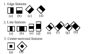
The feature used in a particular classifier is specified by its shape (1a,
2b etc.), position within the region of interest and the scale (this scale is
not the same as the scale used at the detection stage, though these two scales
are multiplied). For example, in case of the third line feature (2c) the
response is calculated as the difference between the sum of image pixels
under the rectangle covering the whole feature (including the two white
stripes and the black stripe in the middle) and the sum of the image
pixels under the black stripe multiplied by 3 in order to compensate for
the differences in the size of areas. The sums of pixel values over a
rectangular regions are calculated rapidly using integral images
(see below and
cvIntegral description).
To see the object detector at work, have a look at HaarFaceDetect demo.
The following reference is for the detection part only. There is a
separate application called haartraining that can train a
cascade of boosted classifiers from a set of samples.
See opencv/apps/haartraining for details.
CvHaarFeature, CvHaarClassifier, CvHaarStageClassifier, CvHaarClassifierCascade
Boosted Haar classifier structures
#define CV_HAAR_FEATURE_MAX 3
/* a haar feature consists of 2-3 rectangles with appropriate weights */
typedef struct CvHaarFeature
{
int tilted; /* 0 means up-right feature, 1 means 45--rotated feature */
/* 2-3 rectangles with weights of opposite signs and
with absolute values inversely proportional to the areas of the rectangles.
if rect[2].weight !=0, then
the feature consists of 3 rectangles, otherwise it consists of 2 */
struct
{
CvRect r;
float weight;
} rect[CV_HAAR_FEATURE_MAX];
}
CvHaarFeature;
/* a single tree classifier (stump in the simplest case) that returns the response for the feature
at the particular image location (i.e. pixel sum over subrectangles of the window) and gives out
a value depending on the responce */
typedef struct CvHaarClassifier
{
int count; /* number of nodes in the decision tree */
/* these are "parallel" arrays. Every index i
corresponds to a node of the decision tree (root has 0-th index).
left[i] - index of the left child (or negated index if the left child is a leaf)
right[i] - index of the right child (or negated index if the right child is a leaf)
threshold[i] - branch threshold. if feature responce is <= threshold, left branch
is chosen, otherwise right branch is chosed.
alpha[i] - output value correponding to the leaf. */
CvHaarFeature* haar_feature;
float* threshold;
int* left;
int* right;
float* alpha;
}
CvHaarClassifier;
/* a boosted battery of classifiers(=stage classifier):
the stage classifier returns 1
if the sum of the classifiers' responces
is greater than threshold and 0 otherwise */
typedef struct CvHaarStageClassifier
{
int count; /* number of classifiers in the battery */
float threshold; /* threshold for the boosted classifier */
CvHaarClassifier* classifier; /* array of classifiers */
/* these fields are used for organizing trees of stage classifiers,
rather than just stright cascades */
int next;
int child;
int parent;
}
CvHaarStageClassifier;
typedef struct CvHidHaarClassifierCascade CvHidHaarClassifierCascade;
/* cascade or tree of stage classifiers */
typedef struct CvHaarClassifierCascade
{
int flags; /* signature */
int count; /* number of stages */
CvSize orig_window_size; /* original object size (the cascade is trained for) */
/* these two parameters are set by cvSetImagesForHaarClassifierCascade */
CvSize real_window_size; /* current object size */
double scale; /* current scale */
CvHaarStageClassifier* stage_classifier; /* array of stage classifiers */
CvHidHaarClassifierCascade* hid_cascade; /* hidden optimized representation of the cascade,
created by cvSetImagesForHaarClassifierCascade */
}
CvHaarClassifierCascade;
All the structures are used for representing a cascaded of boosted Haar
classifiers. The cascade has the following hierarchical structure:
Cascade:
Stage1:
Classifier11:
Feature11
Classifier12:
Feature12
...
Stage2:
Classifier21:
Feature21
...
...
The whole hierarchy can be constructed manually or loaded from a file
using functions cvLoadHaarClassifierCascade
or cvLoad.
cvLoadHaarClassifierCascade
Loads a trained cascade classifier from file
or the classifier database embedded in OpenCV
CvHaarClassifierCascade* cvLoadHaarClassifierCascade(
const char* directory,
CvSize orig_window_size );
- directory
- Name of directory containing the description of a trained cascade
classifier.
- orig_window_size
- Original size of objects the cascade has been
trained on. Note that it is not stored in the cascade and therefore must
be specified separately.
The function cvLoadHaarClassifierCascade
loads a trained cascade of haar classifiers from a file or the classifier
database embedded in OpenCV. The base can be trained using haartraining
application (see opencv/apps/haartraining for details).
The function is obsolete. Nowadays object detection classifiers are stored in
XML or YAML files, rather than in directories. To load cascade from a
file, use cvLoad function.
cvReleaseHaarClassifierCascade
Releases haar classifier cascade
void cvReleaseHaarClassifierCascade( CvHaarClassifierCascade** cascade );
- cascade
- Double pointer to the released cascade.
The pointer is cleared by the function.
The function cvReleaseHaarClassifierCascade
deallocates the cascade that has been created manually or loaded using
cvLoadHaarClassifierCascade or
cvLoad.
cvHaarDetectObjects
Detects objects in the image
typedef struct CvAvgComp
{
CvRect rect; /* bounding rectangle for the object (average rectangle of a group) */
int neighbors; /* number of neighbor rectangles in the group */
}
CvAvgComp;
CvSeq* cvHaarDetectObjects( const CvArr* image, CvHaarClassifierCascade* cascade,
CvMemStorage* storage, double scale_factor=1.1,
int min_neighbors=3, int flags=0,
CvSize min_size=cvSize(0,0) );
- image
- Image to detect objects in.
- cascade
- Haar classifier cascade in internal representation.
- storage
- Memory storage to store the resultant sequence of the
object candidate rectangles.
- scale_factor
- The factor by which the search window is scaled between the subsequent scans,
for example, 1.1 means increasing window by 10%.
- min_neighbors
- Minimum number (minus 1) of neighbor rectangles
that makes up an object. All the groups of a smaller number of rectangles
than
min_neighbors-1 are rejected.
If min_neighbors is 0, the function does not any
grouping at all and returns all the detected candidate rectangles,
which may be useful if the user wants to apply a customized grouping procedure.
- flags
- Mode of operation. Currently the only flag that may be specified is
CV_HAAR_DO_CANNY_PRUNING.
If it is set, the function uses Canny edge detector to reject some image
regions that contain too few or too much edges and thus can not contain the
searched object. The particular threshold values are tuned for face detection
and in this case the pruning speeds up the processing.
- min_size
- Minimum window size. By default, it is set to the size of samples the classifier
has been trained on (~20×20 for face detection).
The function cvHaarDetectObjects finds
rectangular regions in the given image that are likely to contain objects
the cascade has been trained for and returns those regions as
a sequence of rectangles. The function scans the image several
times at different scales (see
cvSetImagesForHaarClassifierCascade). Each time it considers
overlapping regions in the image and applies the classifiers to the regions
using cvRunHaarClassifierCascade.
It may also apply some heuristics to reduce number of analyzed regions, such as
Canny prunning. After it has proceeded and collected the candidate rectangles
(regions that passed the classifier cascade), it groups them and returns a
sequence of average rectangles for each large enough group. The default
parameters (scale_factor=1.1, min_neighbors=3, flags=0)
are tuned for accurate yet slow object detection. For a faster operation on
real video images the settings are: scale_factor=1.2, min_neighbors=2,
flags=CV_HAAR_DO_CANNY_PRUNING, min_size=<minimum possible face size>
(for example, ~1/4 to 1/16 of the image area in case of video conferencing).
Example. Using cascade of Haar classifiers to find objects (e.g. faces).
#include "cv.h"
#include "highgui.h"
CvHaarClassifierCascade* load_object_detector( const char* cascade_path )
{
return (CvHaarClassifierCascade*)cvLoad( cascade_path );
}
void detect_and_draw_objects( IplImage* image,
CvHaarClassifierCascade* cascade,
int do_pyramids )
{
IplImage* small_image = image;
CvMemStorage* storage = cvCreateMemStorage(0);
CvSeq* faces;
int i, scale = 1;
/* if the flag is specified, down-scale the input image to get a
performance boost w/o loosing quality (perhaps) */
if( do_pyramids )
{
small_image = cvCreateImage( cvSize(image->width/2,image->height/2), IPL_DEPTH_8U, 3 );
cvPyrDown( image, small_image, CV_GAUSSIAN_5x5 );
scale = 2;
}
/* use the fastest variant */
faces = cvHaarDetectObjects( small_image, cascade, storage, 1.2, 2, CV_HAAR_DO_CANNY_PRUNING );
/* draw all the rectangles */
for( i = 0; i < faces->total; i++ )
{
/* extract the rectanlges only */
CvRect face_rect = *(CvRect*)cvGetSeqElem( faces, i, 0 );
cvRectangle( image, cvPoint(face_rect.x*scale,face_rect.y*scale),
cvPoint((face_rect.x+face_rect.width)*scale,
(face_rect.y+face_rect.height)*scale),
CV_RGB(255,0,0), 3 );
}
if( small_image != image )
cvReleaseImage( &small_image );
cvReleaseMemStorage( &storage );
}
/* takes image filename and cascade path from the command line */
int main( int argc, char** argv )
{
IplImage* image;
if( argc==3 && (image = cvLoadImage( argv[1], 1 )) != 0 )
{
CvHaarClassifierCascade* cascade = load_object_detector(argv[2]);
detect_and_draw_objects( image, cascade, 1 );
cvNamedWindow( "test", 0 );
cvShowImage( "test", image );
cvWaitKey(0);
cvReleaseHaarClassifierCascade( &cascade );
cvReleaseImage( &image );
}
return 0;
}
cvSetImagesForHaarClassifierCascade
Assigns images to the hidden cascade
void cvSetImagesForHaarClassifierCascade( CvHaarClassifierCascade* cascade,
const CvArr* sum, const CvArr* sqsum,
const CvArr* tilted_sum, double scale );
- cascade
- Hidden Haar classifier cascade, created by
cvCreateHidHaarClassifierCascade.
- sum
- Integral (sum) single-channel image of 32-bit integer format. This image as well as the
two subsequent images are used for fast feature evaluation and
brightness/contrast normalization. They all can be retrieved from input 8-bit
or floating point single-channel image using The function
cvIntegral.
- sqsum
- Square sum single-channel image of 64-bit floating-point format.
- tilted_sum
- Tilted sum single-channel image of 32-bit integer format.
- scale
- Window scale for the cascade. If
scale=1, original window size is
used (objects of that size are searched) - the same size as specified in
cvLoadHaarClassifierCascade
(24x24 in case of "<default_face_cascade>"), if scale=2,
a two times larger window is used (48x48 in case of default face cascade).
While this will speed-up search about four times,
faces smaller than 48x48 cannot be detected.
The function cvSetImagesForHaarClassifierCascade
assigns images and/or window scale to the hidden classifier cascade.
If image pointers are NULL, the previously set images are used further
(i.e. NULLs mean "do not change images"). Scale parameter has no such a "protection" value, but
the previous value can be retrieved by
cvGetHaarClassifierCascadeScale function and reused again. The function
is used to prepare cascade for detecting object of the particular size in the
particular image. The function is called internally by
cvHaarDetectObjects, but it can be called by user if there is a need in
using lower-level function cvRunHaarClassifierCascade.
cvRunHaarClassifierCascade
Runs cascade of boosted classifier at given image location
int cvRunHaarClassifierCascade( CvHaarClassifierCascade* cascade,
CvPoint pt, int start_stage=0 );
- cascade
- Haar classifier cascade.
- pt
- Top-left corner of the analyzed
region. Size of the region is a original window size scaled by the currenly set
scale. The current window size may be retrieved using
cvGetHaarClassifierCascadeWindowSize function.
- start_stage
- Initial zero-based index of the cascade stage to start from.
The function assumes that all the previous stages are passed.
This feature is used internally by
cvHaarDetectObjects for better processor cache utilization.
The function cvRunHaarHaarClassifierCascade
runs Haar classifier cascade at a single image location. Before using this
function the integral images and the appropriate scale (=> window size)
should be set using cvSetImagesForHaarClassifierCascade.
The function returns positive value if the analyzed rectangle passed all the classifier
stages (it is a candidate) and zero or negative value otherwise.
Camera Calibration and 3D Reconstruction
Pinhole Camera Model, Distortion
The functions in this section use so-called pinhole camera model. That is,
a scene view is formed by projecting 3D points into the image plane using perspective transformation.
s*m' = A*[R|t]*M', or
[u] [fx 0 cx] [r11 r12 r13 t1] [X]
s[v] = [0 fy cy]*[r21 r22 r23 t2]*[Y]
[1] [0 0 1] [r31 r32 r33 t2] [Z]
[1]
Where (X, Y, Z) are coordinates of a 3D point in the world coordinate space,
(u, v) are coordinates of point projection in pixels.
A is called a camera matrix, or matrix of intrinsic parameters.
(cx, cy) is a principal point (that is usually at the image center),
and fx, fy are focal lengths expressed in pixel-related units.
Thus, if an image from camera is up-sampled/down-sampled by some factor,
all these parameters (fx, fy, cx and cy) should be scaled
(multiplied/divided, respectively) by the same factor.
The matrix of intrinsic parameters does not depend on the scene viewed
and, once estimated, can be re-used (as long as the focal length is fixed (in case of zoom lens)).
The joint rotation-translation matrix [R|t] is called a matrix of extrinsic parameters.
It is used to describe the camera motion around a static scene, or vice versa,
rigid motion of an object in front of still camera. That is, [R|t] translates coordinates
of a point (X, Y, Z) to some coordinate system, fixed with respect to the camera.
The transformation above is equivalent to the following (when z≠0):
[x] [X]
[y] = R*[Y] + t
[z] [Z]
x' = x/z
y' = y/z
u = fx*x' + cx
v = fy*y' + cy
Real lens usually have some distortion, which major components are radial distorion
and slight tangential distortion. So, the above model is extended as:
[x] [X]
[y] = R*[Y] + t
[z] [Z]
x' = x/z
y' = y/z
x" = x'*(1 + k1r2 + k2r4) + 2*p1x'*y' + p2(r2+2*x'2)
y" = y'*(1 + k1r2 + k2r4) + p1(r2+2*y'2) + 2*p2*x'*y'
where r2 = x'2+y'2
u = fx*x" + cx
v = fy*y" + cy
k1, k2 are radial distortion coefficients,
p1, p2 are tangential distortion coefficients.
Higher-order coefficients are not considered in OpenCV.
The distortion coefficients also do not depend on the scene viewed,
thus they are intrinsic camera parameters.
And they remain the same regardless of the captured image resolution.
The functions below use the above model to
- Project 3D points to the image plane given intrinsic and extrinsic parameters
- Compute extrinsic parameters given intrinsic parameters, a few 3D points and their projections.
- Estimate intrinsic and extrinsic camera parameters from several views of a known calibration pattern
(i.e. every view is described by several 3D-2D point correspodences).
Camera Calibration
ProjectPoints2
Projects 3D points to image plane
void cvProjectPoints2( const CvMat* object_points, const CvMat* rotation_vector,
const CvMat* translation_vector, const CvMat* intrinsic_matrix,
const CvMat* distortion_coeffs, CvMat* image_points,
CvMat* dpdrot=NULL, CvMat* dpdt=NULL, CvMat* dpdf=NULL,
CvMat* dpdc=NULL, CvMat* dpddist=NULL );
- object_points
- The array of object points, 3xN or Nx3,
where N is the number of points in the view.
- rotation_vector
- The rotation vector, 1x3 or 3x1.
- translation_vector
- The translation vector, 1x3 or 3x1.
- intrinsic_matrix
- The camera matrix (A) [fx 0 cx; 0 fy cy; 0 0 1].
- distortion_coeffs
- The vector of distortion coefficients, 4x1 or 1x4
[k1, k2, p1, p2].
If it is NULL, all distortion coefficients are considered 0's.
- image_points
- The output array of image points, 2xN or Nx2,
where N is the total number of points in the view.
- dpdrot
- Optional Nx3 matrix of derivatives of image points with respect to components of the rotation vector.
- dpdt
- Optional Nx3 matrix of derivatives of image points w.r.t. components of the translation vector.
- dpdf
- Optional Nx2 matrix of derivatives of image points w.r.t. fx and fy.
- dpdc
- Optional Nx2 matrix of derivatives of image points w.r.t. cx and cy.
- dpddist
- Optional Nx4 matrix of derivatives of image points w.r.t. distortion coefficients.
The function cvProjectPoints2 computes projections of 3D points to the image plane given
intrinsic and extrinsic camera parameters. Optionally, the function computes jacobians - matrices of
partial derivatives of image points as functions of all the input parameters w.r.t. the particular parameters,
intrinsic and/or extrinsic. The jacobians are used during the global optimization in
cvCalibrateCamera2 and
cvFindExtrinsicCameraParams2.
The function itself is also used to compute back-projection error for with current
intrinsic and extrinsic parameters.
Note, that with intrinsic and/or extrinsic parameters set to special values,
the function can be used to compute just extrinsic transformation or just intrinsic
transformation (i.e. distortion of a sparse set of points).
FindHomography
Finds perspective transformation between two planes
void cvFindHomography( const CvMat* src_points,
const CvMat* dst_points,
CvMat* homography );
- src_points
- Point coordinates in the original plane, 2xN, Nx2, 3xN or Nx3 array
(the latter two are for representation in homogenious coordinates),
where N is the number of points.
- dst_points
- Point coordinates in the destination plane, 2xN, Nx2, 3xN or Nx3 array
(the latter two are for representation in homogenious coordinates)
- homography
- Output 3x3 homography matrix.
The function cvFindHomography finds perspective transformation H=||hij|| between the source
and the destination planes:
[x'i] [xi]
si[y'i]~H*[yi]
[1 ] [ 1]
So that the back-projection error is minimized:
sum_i((x'i-(h11*xi + h12*yi + h13)/(h31*xi + h32*yi + h33))2+
(y'i-(h21*xi + h22*yi + h23)/(h31*xi + h32*yi + h33))2) -> min
The function is used to find initial intrinsic and extrinsic matrices.
Homography matrix is determined up to a scale, thus it is normalized to make h33=1.
CalibrateCamera2
Finds intrinsic and extrinsic camera parameters using calibration pattern
void cvCalibrateCamera2( const CvMat* object_points, const CvMat* image_points,
const CvMat* point_counts, CvSize image_size,
CvMat* intrinsic_matrix, CvMat* distortion_coeffs,
CvMat* rotation_vectors=NULL, CvMat* translation_vectors=NULL,
int flags=0 );
- object_points
- The joint matrix of object points, 3xN or Nx3,
where N is the total number of points in all views.
- image_points
- The joint matrix of corresponding image points, 2xN or Nx2,
where N is the total number of points in all views.
- point_counts
- Vector containing numbers of points in each particular view,
1xM or Mx1, where M is the number of a scene views.
- image_size
- Size of the image, used only to initialize intrinsic camera matrix.
- intrinsic_matrix
- The output camera matrix (A) [fx 0 cx; 0 fy cy; 0 0 1].
If
CV_CALIB_USE_INTRINSIC_GUESS and/or
CV_CALIB_FIX_ASPECT_RATION are specified, some or all
of fx, fy, cx, cy must be initialized.
- distortion_coeffs
- The output 4x1 or 1x4 vector of distortion coefficients
[k1, k2, p1, p2].
- rotation_vectors
- The output 3xM or Mx3 array of rotation vectors
(compact representation of rotation matrices,
see cvRodrigues2).
- translation_vectors
- The output 3xM or Mx3 array of translation vectors.
- flags
- Different flags, may be 0 or combination of the following values:
CV_CALIB_USE_INTRINSIC_GUESS - intrinsic_matrix contains
valid initial values of fx, fy, cx, cy that are optimized further.
Otherwise, (cx, cy) is initially set to the image center
(image_size is used here),
and focal distances are computed in some least-squares fashion.
Note, that if intrinsic parameters are known, there is no need to use this function.
Use cvFindExtrinsicCameraParams2 instead.
CV_CALIB_FIX_PRINCIPAL_POINT - The principal point is not changed during the global
optimization, it stays at the center and at the other location specified (when
CV_CALIB_USE_INTRINSIC_GUESS is set as well).
CV_CALIB_FIX_ASPECT_RATIO - The optimization procedure consider only
one of fx and fy as independent variable and keeps the aspect ratio
fx/fy the same as it was set initially in intrinsic_matrix.
In this case the actual initial values of (fx, fy) are either taken from the matrix
(when CV_CALIB_USE_INTRINSIC_GUESS is set) or estimated somehow (in the latter case
fx, fy may be set to arbitrary values, only their ratio is used).
CV_CALIB_ZERO_TANGENT_DIST - Tangential distortion coefficients are set to
zeros and do not change during the optimization.
The function cvCalibrateCamera2 estimates intrinsic camera parameters and extrinsic parameters
for each of the views.
The coordinates of 3D object points and their correspondent 2D projections in each view
must be specified. That may be achieved by using an object with known geometry and easily detectable
feature points. Such an object is called a calibration rig or calibration pattern, and OpenCV has built-in
support for a chessboard as a calibration rig
(see cvFindChessboardCorners).
Currently, initialization of inrtrinsic parameters (when CV_CALIB_USE_INTRINSIC_GUESS
is not set) is only implemented for planar calibration rigs (z-coordinates of object points
must be all 0's or all 1's). 3D rigs can still be used as long as initial intrinsic_matrix
is provided. After the initial values of intrinsic and extrinsic parameters are computed, they are
optimized to minimize the total back-projection error - the sum of squared differences between the
actual coordinates of image points and the ones computed using
cvProjectPoints2.
FindExtrinsicCameraParams2
Finds extrinsic camera parameters for particular view
void cvFindExtrinsicCameraParams2( const CvMat* object_points,
const CvMat* image_points,
const CvMat* intrinsic_matrix,
const CvMat* distortion_coeffs,
CvMat* rotation_vector,
CvMat* translation_vector );
- object_points
- The array of object points, 3xN or Nx3,
where N is the number of points in the view.
- image_points
- The array of corresponding image points, 2xN or Nx2,
where N is the number of points in the view.
- intrinsic_matrix
- The camera matrix (A) [fx 0 cx; 0 fy cy; 0 0 1].
- distortion_coeffs
- The vector of distortion coefficients, 4x1 or 1x4
[k1, k2, p1, p2].
If it is NULL, all distortion coefficients are considered 0's.
- rotation_vector
- The output 3x1 or 1x3 rotation vector
(compact representation of a rotation matrix,
see cvRodrigues2).
- translation_vector
- The output 3x1 or 1x3 translation vector.
The function cvFindExtrinsicCameraParams2 estimates extrinsic camera parameters
using known intrinsic parameters and and extrinsic parameters
for each view. The coordinates of 3D object points and their correspondent 2D projections
must be specified. This function also minimizes back-projection error.
Rodrigues2
Converts rotation matrix to rotation vector or vice versa
int cvRodrigues2( const CvMat* src, CvMat* dst, CvMat* jacobian=0 );
- src
- The input rotation vector (3x1 or 1x3) or rotation matrix (3x3).
- dst
- The output rotation matrix (3x3) or rotation vector (3x1 or 1x3), respectively.
- jacobian
- Optional output Jacobian matrix, 3x9 or 9x3 - partial derivatives of
the output array components w.r.t the input array components.
The function cvRodrigues2 converts a rotation vector to rotation matrix or
vice versa. Rotation vector is a compact representation of rotation matrix.
Direction of the rotation vector is the rotation axis and the length of the vector is the rotation
angle around the axis.
The rotation matrix R, corresponding to the rotation vector r,
is computed as following:
theta <- norm(r)
r <- r/theta
[0 -rz ry]
R = cos(theta)*I + (1-cos(theta))*rrT + sin(theta)*[rz 0 -rx]
[ry rx 0]
Inverse transformation can also be done easily as
[0 -rz ry]
sin(theta)*[rz 0 -rx] = (R - RT)/2
[ry rx 0]
Rotation vector is a convenient representation of a rotation matrix as a matrix with only 3 degrees of freedom.
The representation is used in the global optimization procedures inside
cvFindExtrinsicCameraParams2 and
cvCalibrateCamera2.
Undistort2
Transforms image to compensate lens distortion
void cvUndistort2( const CvArr* src, CvArr* dst,
const CvMat* intrinsic_matrix,
const CvMat* distortion_coeffs );
- src
- The input (distorted) image.
- dst
- The output (corrected) image.
- intrinsic_matrix
- The camera matrix (A) [fx 0 cx; 0 fy cy; 0 0 1].
- distortion_coeffs
- The vector of distortion coefficients, 4x1 or 1x4
[k1, k2, p1, p2].
The function cvUndistort2 transforms the image to compensate radial and tangential lens distortion.
The camera matrix and distortion parameters can be determined using
cvCalibrateCamera2.
For every pixel in the output image the function computes coordinates of the corresponding location in the input
image using the formulae in the section beginning. Then, the pixel value is computed using bilinear interpolation.
If the resolution of images is different from what was used at the calibration stage,
fx, fy, cx and cy need to be adjusted appropriately, while
the distortion coefficients remain the same.
InitUndistortMap
Computes undistorion map
void cvInitUndistortMap( const CvMat* intrinsic_matrix,
const CvMat* distortion_coeffs,
CvArr* mapx, CvArr* mapy );
- intrinsic_matrix
- The camera matrix (A) [fx 0 cx; 0 fy cy; 0 0 1].
- distortion_coeffs
- The vector of distortion coefficients, 4x1 or 1x4
[k1, k2, p1, p2].
- mapx
- The output array of x-coordinates of the map.
- mapy
- The output array of y-coordinates of the map.
The function cvInitUndistortMap pre-computes the undistortion map
- coordinates of the corresponding pixel in the distorted image for every pixel in the corrected image.
Then, the map (together with input and output images) can be passed
to cvRemap function.
FindChessboardCorners
Finds positions of internal corners of the chessboard
int cvFindChessboardCorners( const void* image, CvSize pattern_size,
CvPoint2D32f* corners, int* corner_count=NULL,
int flags=CV_CALIB_CB_ADAPTIVE_THRESH );
- image
- Source chessboard view; it must be 8-bit grayscale or color image.
- pattern_size
- The number of inner corners per chessboard row and column.
- corners
- The output array of corners detected.
- corner_count
- The output corner counter. If it is not NULL, the function stores
there the number of corners found.
- flags
- Various operation flags, can be 0 or a combination of the following values:
CV_CALIB_CB_ADAPTIVE_THRESH - use adaptive thresholding to convert the
image to black-n-white, rather than a fixed threshold level (computed from the average image brightness).
CV_CALIB_CB_NORMALIZE_IMAGE - normalize the image using
cvNormalizeHist before applying fixed or adaptive thresholding.
CV_CALIB_CB_FILTER_QUADS - use additional criteria (like contour area, perimeter,
square-like shape) to filter out false quads that are extracted at the contour retrieval stage.
The function cvFindChessboardCorners attempts to determine whether the input
image is a view of the chessboard pattern and locate internal chessboard
corners. The function returns non-zero value if all the corners have been found
and they have been placed in a certain order (row by row, left to right in every
row), otherwise, if the function fails to find all the corners or reorder them,
it returns 0. For example, a regular chessboard has 8 x 8 squares and 7
x 7 internal corners, that is, points, where the black squares touch each other.
The coordinates detected are approximate, and to determine their position more accurately,
the user may use the function cvFindCornerSubPix.
DrawChessBoardCorners
Renders the detected chessboard corners
void cvDrawChessboardCorners( CvArr* image, CvSize pattern_size,
CvPoint2D32f* corners, int count,
int pattern_was_found );
- image
- The destination image; it must be 8-bit color image.
- pattern_size
- The number of inner corners per chessboard row and column.
- corners
- The array of corners detected.
- count
- The number of corners.
- pattern_was_found
- Indicates whether the complete board was found (≠0) or not (=0). One may just
pass the return value cvFindChessboardCorners here.
The function cvDrawChessboardCorners draws the individual chessboard corners detected (as red circles)
in case if the board was not found (pattern_was_found=0) or the colored corners connected with lines
when the board was found (pattern_was_found≠0).
Pose Estimation
CreatePOSITObject
Initializes structure containing object information
CvPOSITObject* cvCreatePOSITObject( CvPoint3D32f* points, int point_count );
- points
- Pointer to the points of the 3D object model.
- point_count
- Number of object points.
The function cvCreatePOSITObject allocates memory for the object structure and
computes the object inverse matrix.
The preprocessed object data is stored in the structure CvPOSITObject, internal
for OpenCV, which means that the user cannot directly access the structure data.
The user may only create this structure and pass its pointer to the function.
Object is defined as a set of points given in a coordinate system. The function
cvPOSIT computes a vector that begins at a camera-related coordinate system center
and ends at the points[0] of the object.
Once the work with a given object is finished, the function
cvReleasePOSITObject
must be called to free memory.
POSIT
Implements POSIT algorithm
void cvPOSIT( CvPOSITObject* posit_object, CvPoint2D32f* image_points, double focal_length,
CvTermCriteria criteria, CvMatr32f rotation_matrix, CvVect32f translation_vector );
- posit_object
- Pointer to the object structure.
- image_points
- Pointer to the object points projections on the 2D image plane.
- focal_length
- Focal length of the camera used.
- criteria
- Termination criteria of the iterative POSIT algorithm.
- rotation_matrix
- Matrix of rotations.
- translation_vector
- Translation vector.
The function cvPOSIT implements POSIT algorithm. Image coordinates are given in a
camera-related coordinate system. The focal length may be retrieved using camera
calibration functions. At every iteration of the algorithm new perspective
projection of estimated pose is computed.
Difference norm between two projections is the maximal distance between
corresponding points. The parameter criteria.epsilon serves to stop the
algorithm if the difference is small.
ReleasePOSITObject
Deallocates 3D object structure
void cvReleasePOSITObject( CvPOSITObject** posit_object );
- posit_object
- Double pointer to
CvPOSIT structure.
The function cvReleasePOSITObject releases memory previously allocated by the
function cvCreatePOSITObject.
CalcImageHomography
Calculates homography matrix for oblong planar object (e.g. arm)
void cvCalcImageHomography( float* line, CvPoint3D32f* center,
float* intrinsic, float* homography );
- line
- the main object axis direction (vector (dx,dy,dz)).
- center
- object center ((cx,cy,cz)).
- intrinsic
- intrinsic camera parameters (3x3 matrix).
- homography
- output homography matrix (3x3).
The function cvCalcImageHomography calculates the homography matrix for the initial
image transformation from image plane to the plane, defined by 3D oblong object line (See
Figure 6-10 in OpenCV Guide 3D Reconstruction Chapter).
Epipolar Geometry
FindFundamentalMat
Calculates fundamental matrix from corresponding points in two images
int cvFindFundamentalMat( const CvMat* points1,
const CvMat* points2,
CvMat* fundamental_matrix,
int method=CV_FM_RANSAC,
double param1=1.,
double param2=0.99,
CvMat* status=NULL);
- points1
- Array of the first image points of
2xN, Nx2, 3xN or Nx3 size
(where N is number of points).
Multi-channel 1xN or Nx1 array is also acceptable.
The point coordinates should be floating-point (single or double precision)
- points2
- Array of the second image points of the same size and format as
points1
- fundamental_matrix
- The output fundamental matrix or matrices. The size should be 3x3 or 9x3
(7-point method may return up to 3 matrices).
- method
- Method for computing the fundamental matrix
- CV_FM_7POINT - for 7-point algorithm. N == 7
- CV_FM_8POINT - for 8-point algorithm. N >= 8
- CV_FM_RANSAC - for RANSAC algorithm. N >= 8
- CV_FM_LMEDS - for LMedS algorithm. N >= 8
- param1
- The parameter is used for RANSAC or LMedS methods only.
It is the maximum distance from point to epipolar line in pixels,
beyond which the point is considered an outlier and is not used
for computing the final fundamental matrix.
Usually it is set to 0.5 or 1.0.
- param2
- The parameter is used for RANSAC or LMedS methods only.
It denotes the desirable level of confidence that the matrix
is correct.
- status
- The optional output array of N elements,
every element of which is set to 0 for outliers
and to 1 for the other points.
The array is computed only in RANSAC and LMedS methods.
For other methods it is set to all 1’s.
The epipolar geometry is described by the following equation:
p2T*F*p1=0,
where F is fundamental matrix, p1 and p2 are corresponding
points in the first and the second images, respectively.
The function cvFindFundamentalMat calculates fundamental matrix using one of four
methods listed above and returns the number of fundamental matrices found (1 or 3) and 0,
if no matrix is found.
The calculated fundamental matrix may be passed further to cvComputeCorrespondEpilines
that finds epipolar lines corresponding to the specified points.
Example. Estimation of fundamental matrix using RANSAC algorithm
int point_count = 100;
CvMat* points1;
CvMat* points2;
CvMat* status;
CvMat* fundamental_matrix;
points1 = cvCreateMat(1,point_count,CV_32FC2);
points2 = cvCreateMat(1,point_count,CV_32FC2);
status = cvCreateMat(1,point_count,CV_8UC1);
/* Fill the points here ... */
for( i = 0; i < point_count; i++ )
{
points1->data.db[i*2] = <x1,i>;
points1->data.db[i*2+1] = <y1,i>;
points2->data.db[i*2] = <x2,i>;
points2->data.db[i*2+1] = <y2,i>;
}
fundamental_matrix = cvCreateMat(3,3,CV_32FC1);
int fm_count = cvFindFundamentalMat( points1,points2,fundamental_matrix,
CV_FM_RANSAC,1.0,0.99,status );
ComputeCorrespondEpilines
For points in one image of stereo pair computes the corresponding epilines in the other image
void cvComputeCorrespondEpilines( const CvMat* points,
int which_image,
const CvMat* fundamental_matrix,
CvMat* correspondent_lines);
- points
- The input points.
2xN, Nx2, 3xN or Nx3 array (where N number of points).
Multi-channel 1xN or Nx1 array is also acceptable.
- which_image
- Index of the image (1 or 2) that contains the
points
- fundamental_matrix
- Fundamental matrix
- correspondent_lines
- Computed epilines,
3xN or Nx3 array
For every point in one of the two images of stereo-pair the function
cvComputeCorrespondEpilines finds equation of a line that contains
the corresponding point (i.e. projection of the same 3D point) in the other image.
Each line is encoded by a vector of 3 elements l=[a,b,c]T, so that:
lT*[x, y, 1]T=0, or
a*x + b*y + c = 0
From the fundamental matrix definition (see cvFindFundamentalMatrix
discussion), line l2 for a point p1
in the first image (which_image=1) can be computed as:
l2=F*p1
and the line l1 for a point p2
in the second image (which_image=1) can be computed as:
l1=FT*p2
Line coefficients are defined up to a scale.
They are normalized (a2+b2=1)
are stored into correspondent_lines.
ConvertPointsHomogenious
Convert points to/from homogenious coordinates
void cvConvertPointsHomogenious( const CvMat* src, CvMat* dst );
- src
- The input point array,
2xN, Nx2, 3xN, Nx3, 4xN or Nx4
(where N is the number of points).
Multi-channel 1xN or Nx1 array is also acceptable.
- dst
- The output point array, must contain the same number of points as the input;
The dimensionality must be the same, 1 less or 1 more than the input, and
also within 2..4.
The function cvConvertPointsHomogenious converts 2D or 3D points
from/to homogenious coordinates, or simply copies or transposes the array.
In case if the input array dimensionality is larger than the output,
each point coordinates are divided by the last coordinate:
(x,y[,z],w) -> (x',y'[,z']):
x' = x/w
y' = y/w
z' = z/w (if output is 3D)
If the output array dimensionality is larger, an extra 1 is appended to each point.
(x,y[,z]) -> (x,y[,z],1)
Otherwise, the input array is simply copied (with optional tranposition) to the output.
Note that, because the function accepts a large variety of array layouts, it
may report an error when input/output array dimensionality is ambiguous.
It is always safe to use the function with number of points N>=5, or
to use multi-channel Nx1 or 1xN arrays.
Alphabetical List of Functions
2
2DRotationMatrix
A
Acc
ApproxChains
ArcLength
AdaptiveThreshold
ApproxPoly
B
BoundingRect
BoxPoints
C
D
Dilate
DistTransform
DrawChessBoardCorners
E
EndFindContours
EqualizeHist
Erode
F
Filter2D
FindExtrinsicCameraParams2
FindNextContour
FindChessboardCorners
FindFundamentalMat
FitEllipse
FindContours
FindHomography
FitLine2D
FindCornerSubPix
FindNearestPoint2D
FloodFill
G
H
HaarDetectObjects
HoughCircles
HoughLines2
I
InitUndistortMap
Inpaint
Integral
K
KalmanCorrect
KalmanPredict
L
Laplace
LoadHaarClassifierCascade
LogPolar
M
MakeHistHeaderForArray
MaxRect
Moments
MatchContourTrees
MeanShift
MorphologyEx
MatchShapes
MinAreaRect2
MultiplyAcc
MatchTemplate
MinEnclosingCircle
N
NormalizeHist
P
POSIT
PreCornerDetect
PyrMeanShiftFiltering
PointPolygonTest
ProjectPoints2
PyrSegmentation
PointSeqFromMat
PyrDown
PyrUp
Q
QueryHistValue_*D
R
ReadChainPoint
ReleaseKalman
Resize
ReleaseConDensation
ReleasePOSITObject
Rodrigues2
ReleaseHaarClassifierCascade
ReleaseStructuringElement
RunHaarClassifierCascade
ReleaseHist
Remap
RunningAvg
S
T
ThreshHist
Threshold
U
Undistort2
UpdateMotionHistory
W
WarpAffine
WarpPerspective
Watershed
Bibliography
This bibliography provides a list of publications that were might be useful to
the OpenCV users. This list is not complete; it serves only
as a starting point.
- [Borgefors86]
Gunilla Borgefors, "Distance Transformations in Digital Images". Computer Vision, Graphics and Image Processing 34, 344-371 (1986).
- [Bouguet00]
Jean-Yves Bouguet. Pyramidal Implementation of the Lucas Kanade Feature Tracker.
The paper is included into OpenCV distribution (algo_tracking.pdf)
- [Bradski98]
G.R. Bradski. Computer vision face tracking as a component of a perceptual
user interface. In Workshop on Applications of Computer Vision, pages 214�219,
Princeton, NJ, Oct. 1998.
Updated version can be found at
http://www.intel.com/technology/itj/q21998/articles/art_2.htm.
Also, it is included into OpenCV distribution (camshift.pdf)
- [Bradski00] G. Bradski and J. Davis. Motion Segmentation and Pose Recognition
with Motion History Gradients. IEEE WACV'00, 2000.
- [Burt81] P. J. Burt, T. H. Hong, A. Rosenfeld. Segmentation and Estimation of
Image Region Properties Through Cooperative Hierarchical Computation. IEEE Tran.
On SMC, Vol. 11, N.12, 1981, pp. 802-809.
- [Canny86] J. Canny. A Computational Approach to Edge Detection, IEEE Trans. on
Pattern Analysis and Machine Intelligence, 8(6), pp. 679-698 (1986).
- [Davis97] J. Davis and Bobick. The Representation and Recognition of Action
Using Temporal Templates. MIT Media Lab Technical Report 402, 1997.
- [DeMenthon92] Daniel F. DeMenthon and Larry S. Davis. Model-Based Object Pose in
25 Lines of Code. In Proceedings of ECCV '92, pp. 335-343, 1992.
- [Felzenszwalb04]
Pedro F. Felzenszwalb and Daniel P. Huttenlocher.
Distance Transforms of Sampled Functions.
Cornell Computing and Information Science TR2004-1963.
- [Fitzgibbon95] Andrew W. Fitzgibbon, R.B.Fisher. A Buyer’s Guide to Conic
Fitting. Proc.5th British Machine Vision Conference, Birmingham, pp. 513-522,
1995.
- [Ford98] Adrian Ford, Alan Roberts. Colour Space Conversions.
http://www.poynton.com/PDFs/coloureq.pdf
- [Horn81]
Berthold K.P. Horn and Brian G. Schunck. Determining Optical Flow.
Artificial Intelligence, 17, pp. 185-203, 1981.
- [Hu62] M. Hu. Visual Pattern Recognition by Moment Invariants, IRE Transactions
on Information Theory, 8:2, pp. 179-187, 1962.
- [Iivarinen97]
Jukka Iivarinen, Markus Peura, Jaakko Srel, and Ari Visa.
Comparison of Combined Shape Descriptors for Irregular Objects, 8th British Machine Vision Conference, BMVC'97.
http://www.cis.hut.fi/research/IA/paper/publications/bmvc97/bmvc97.html
- [Jahne97] B. Jahne. Digital Image Processing. Springer, New York, 1997.
- [Lucas81]
Lucas, B., and Kanade, T. An Iterative Image
Registration Technique with an Application to Stereo
Vision, Proc. of 7th International Joint Conference on
Artificial Intelligence (IJCAI), pp. 674-679.
- [Kass88] M. Kass, A. Witkin, and D. Terzopoulos. Snakes: Active Contour Models,
International Journal of Computer Vision, pp. 321-331, 1988.
- [Lienhart02]
Rainer Lienhart and Jochen Maydt.
An Extended Set of Haar-like Features for Rapid Object Detection.
IEEE ICIP 2002, Vol. 1, pp. 900-903, Sep. 2002.
This paper, as well as the extended technical report, can be retrieved at
http://www.lienhart.de/Publications/publications.html
- [Matas98] J.Matas, C.Galambos, J.Kittler. Progressive Probabilistic Hough
Transform. British Machine Vision Conference, 1998.
- [Meyer92]
Meyer, F. (1992). Color image segmentation. In Proceedings of the International Conference on Image Processing and its Applications, pages 303--306.
- [Rosenfeld73] A. Rosenfeld and E. Johnston. Angle Detection on Digital Curves.
IEEE Trans. Computers, 22:875-878, 1973.
- [RubnerJan98] Y. Rubner. C. Tomasi, L.J. Guibas. Metrics for Distributions with
Applications to Image Databases. Proceedings of the 1998 IEEE International
Conference on Computer Vision, Bombay, India, January 1998, pp. 59-66.
- [RubnerSept98]
Y. Rubner. C. Tomasi, L.J. Guibas. The Earth Mover’s Distance as a
Metric for Image Retrieval. Technical Report STAN-CS-TN-98-86,
Department of Computer Science, Stanford University, September
1998.
- [RubnerOct98] Y. Rubner. C. Tomasi. Texture Metrics. Proceeding of the IEEE
International Conference on Systems, Man, and Cybernetics, San-Diego, CA,
October 1998, pp. 4601-4607.
http://robotics.stanford.edu/~rubner/publications.html
- [Serra82] J. Serra. Image Analysis and Mathematical Morphology. Academic Press,
1982.
- [Schiele00] Bernt Schiele and James L. Crowley. Recognition without
Correspondence Using Multidimensional Receptive Field Histograms. In
International Journal of Computer Vision 36 (1), pp. 31-50, January 2000.
- [Suzuki85] S. Suzuki, K. Abe. Topological Structural Analysis of Digital Binary
Images by Border Following. CVGIP, v.30, n.1. 1985, pp. 32-46.
- [Teh89] C.H. Teh, R.T. Chin. On the Detection of Dominant Points on Digital
Curves. - IEEE Tr. PAMI, 1989, v.11, No.8, p. 859-872.
- [Telea04]
A. Telea, "An image inpainting technique based on the fast marching method,"
J. Graphics Tools, vol.9, no.1, pp.25�36, 2004.
- [Trucco98] Emanuele Trucco, Alessandro Verri. Introductory Techniques for 3-D
Computer Vision. Prentice Hall, Inc., 1998.
- [Viola01]
Paul Viola and Michael J. Jones.
Rapid Object Detection using a Boosted Cascade of Simple Features. IEEE CVPR, 2001.
The paper is available online at
http://www.ai.mit.edu/people/viola/
- [Welch95]
Greg Welch, Gary Bishop. An Introduction To the Kalman Filter.
Technical Report TR95-041, University of North Carolina at Chapel Hill, 1995.
Online version is available at
http://www.cs.unc.edu/~welch/kalman/kalmanIntro.html
- [Williams92] D. J. Williams and M. Shah. A Fast Algorithm for Active Contours
and Curvature Estimation. CVGIP: Image Understanding, Vol. 55, No. 1, pp. 14-26,
Jan., 1992. http://www.cs.ucf.edu/~vision/papers/shah/92/WIS92A.pdf.
- [Yuen03]
H.K. Yuen, J. Princen, J. Illingworth and J. Kittler.
Comparative study of Hough Transform methods for circle finding.
http://www.sciencedirect.com/science/article/B6V09-48TCV4N-5Y/2/91f551d124777f7a4cf7b18325235673
- [Yuille89] A.Y.Yuille, D.S.Cohen, and P.W.Hallinan. Feature Extraction from
Faces Using Deformable Templates in CVPR, pp. 104-109, 1989.
- [Zhang96] Z. Zhang. Parameter Estimation Techniques: A Tutorial with Application
to Conic Fitting, Image and Vision Computing Journal, 1996.
- [Zhang99] Z. Zhang. Flexible Camera Calibration By Viewing a Plane From Unknown
Orientations. International Conference on Computer Vision (ICCV'99), Corfu,
Greece, pages 666-673, September 1999.
- [Zhang00] Z. Zhang. A Flexible New Technique for Camera Calibration. IEEE
Transactions on Pattern Analysis and Machine Intelligence, 22(11):1330-1334,
2000.